In my experience the optical stops are highly repeatable as long as nothing changes or gets obscured. But half a mil might be asking for a lot, because ultimately they’re taking the analog signal of how much light is getting across the gap and doing a threshold to turn that into a digital signal, so electrical noise, power-supply ripple, ambient light blah blah blah. At least some of them do a quick home, then back off and run much more slowly to get the final position.
Inductive stops also highly repeatable unless the configuration of inductive materials around the stop changes or the electrical situation changes. BTDT.
Which is a longwinded way of saying “Yeah, you really are going to have to run your own tests.”
Hehehe, those results that have you repeating the operation just for the enjoyment of the giggles it inspires are golden!
It may be a small thing, but it’s effect on the psyche is huge!
My mill is roughly +/- 0.001 in any axis, which is nice at times but re-referencing to establish part zeroes with a 3D probe is very fast, even manually. Faster yet with an electronic probe.
The lathe is much harder, or at least more time consuming, to re-establish part (G54) zeroes and an error of 0.001-in in X gives you a 0.002-in error in diameter, so a more accurate and repeatable way to reference can pay some significant dividends, especially with tendency to accidentally bump the E-stop switches, which forces a re-reference by the control software.
I can identify with your test procedure and the outcome. Giggles are so much better than spewing oaths when something goes belly up.
That’s often the case when you are fussy about results so perhaps it’s best to just get it done. Just part of the game I guess. Metal swarf should mostly stay away from the switch locations, at least for the materials I’ve turned so far, so at least that is not likely to be an issue.
@dan I think you’re still missing the basic question or I must still be missing something(?) If there’s no physical zero guide on the bed, how would we know the exact size for a guide and where to place it in order to ‘put the material in the same place’ AND at the correct angle?
Dan has been a bit busy recently…he might be out of pocket.
Are you talking about just engraving on something, or do you want to cut it out of larger material? If you’re cutting it out, you just put the new sheet back in the same place, take a quick look to make sure that all the cut lines still fall on the material, and resend the job. Any engraving inside of the cut lines is going to line up perfectly with the cut lines, as promised.
If you are wanting to laser engrave on one or more pre-cut objects that already exist, Dan has recently explained how the Glowforge software will allow for several options here, using engraving on almonds as an example:
I’d personally probably just create a jig, but there are apparently several other options available to us inside the software.
Say I have an object that is already engraved with a specific pattern, and I need to take exactly 3mm off of the top and left sides, anything more or less will ruin the piece. with a home position of 0,0 that is exact, it will be easy to do every time without worry, because we can set up something in the corner to align it with.
If there is no consistent home, to get an exact cut, we will have to make a new jig EVERY TIME. massive pain in the butt. That is to say there is even the ability to use the last home position as the home position on the next cut.
I have to do this on my CNC machine and would prefer not to, but on my chinese laser I cut a corner piece when I first got it so that I know where 0,0 is and I can cut a 4mm piece off of something without a care. Repeatably. Not being able to do this on a glowforge would really take a lot from the product. Its almost like turning a digital machine analog, and that would be a terrible thing for accuracy, and quite a shame
aye, having a whole scrap box full of square corner jigs just so you can have a 0,0 to make an accurate cut sounds like a lot of unnecessary waste in both time and materials to me.
Would a tape guide, as @dan an has mentioned, not work for your case? an upside-down “L” in the top left corner to show you where the software automatically drops the top left corner of your design when you “print” it? I’m guessing you could put some wider tape up in that corner, create a design that is just the “L” and let it fall into that 0,0 position (that is, not move it,) “print,” then remove the bit of tape that is outside the laserable area. You could add the step of using the tape to help you figure out how to put in physical edges if that is what you are looking for and if that is practical given the internals of the machine. What is a specific example of your case?
When the lid closes you get a picture of the bed automatically and you have to use the UI to send print job, why wouldn’t you just check alignment before you hit print?
So if you have 45 odd shaped parts that all needed engraving. You would want to manually adjust each graphic with the virtual viewfinder vs. having a known start position that is static and consistent with every job? And where you can fire and forget?
I don’t want you to do anything I was just trying to help with a suggestion lol. I am new to laser anything but seems easy to me but I guess I’ll find out soon
@karaelena@takitus
When you set your laser to 0,0, what is your tool pointed at? That is, what physical characteristic of the bed does it reference, that you can accurately laser-engrave your material without worrying that your material is a fraction of an inch offset or fraction of a degree rotated? In my experience on many other lasers, it references a random spot on the grate - nothing in particular - and then I have to put a mark there. If I ever want accuracy better than an eyeball, I do it by cutting a piece-shaped hole in material and then dropping the piece in there.
Would love to better understand your use case & existing solutions.
A use case would be wanting to laser pre-cut rectangular cork coasters. If you want to laser 20 off with the same image, having a known reference corner that you can just place the coaster against would be very useful.
Once placed in the corner, it would be great to just be able to hit the forge button for the previously aligned image to be placed in the same alignment on the coaster, with repeatability.
Having the reference corner would save making jigs and the issue of the jigs potentially moving.
Here are some solutions that I came up with that solves your issue…
Solution #1: Situate a piece of wood or acrylic about the length of the bed against the back wall of the Glowforge, then using Inkscape, Illistrator or a CAD program, I would cut out 5, 10 or even all 20 spaces for the coaster’s to fit into. Then I would iterate the engraved image appropriately.
Solution #2: In your base design use a “non engrave, non cut” color that is the size and shape of your coaster blank material. Then situate the image that you want to engrave with in the boundary. Then when you copy each image to your blank material just line up the bounding box with the edges of the material and adjust for rotation.
Solution #3: Use a larger piece of material for your coaster’s base, Cut each item out of it. In your cut file arrange all of your cut and engrave pieces in such a way to maximize material usage and minimize waste. This way when the material is placed on the bed all you would need to do would be to move/rotate the image OR the material minimally to get optimal alignment.
Overall: The bonuses of the camera alignment system of the Glowforge is that a 0.0 point is not necessary since you can manually align the project onto the material it’s self. This fact is also what has me personally MOST excited about the Glowforge.
I’m going to take a wild guess at the alignment methodology. A great deal of brain power has been spent worrying about head positional knowledge and whether a particular use case is built in.
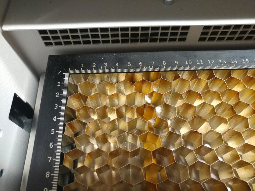
I’m guessing here…the GF doesn’t have a startup 0,0 or anything more than a rough idea of where the head is initially. It probably only knows a rough stow position so that the head can move in a proper direction after startup. The overhead camera determines a fairly accurate head position after startup. But there will be some slop in this position. This 0,0 accuracy is limited by the resolution of the overhead camera. It is independent of the internal honeycomb or any other physical mark. It may be slightly different for each and every GF unit. Do not confuse the high accuracy placement of the laser spot after 0,0 has been determined with the lesser accuracy of the initial position. 99.5% of us don’t care if initial 0,0 is off by 0.001" or 0.1". We visually align the design with the material. The digital image from the cameras will aid that process through position and zoom capabilities. For those that believe they need a predetermined unchanging 0,0 at startup I think in real world operations you will find the GF methodology to be different, but more than OK. For most of us the GF method will be far more user friendly.
I’ve more or less decided to adopt a “wait and see” attitude.
Whatever the machine does might be better than having a single origin. A single 0,0 point origin didn’t do anything as far as rotation went, and it was ridiculously easy to get a cut slightly out of skew when we tried to do PnC alignments with some of the digital cutters.
We would probably need to figure out some way to get a 3 point Registration system going, to use with the camera, but I can’t for the life of me figure out how you could do that consistently with something that isn’t printed, and a standard shape like a sheet of paper or a rectangle. (I always circle back to needing a physical jig of some sort, be it paper, cardboard or wood.)
I have faith that the folks here are clever enough to figure out a way to make it work until GF can look into something like 3-Point Registration though, and I plan to experiment with it after I receive the laser and can see what it does, and what the limitations are.
(The suggestion to look into 3-Pt Reg is in the hopper from way back…I put it up for grabs shortly after joining the forum, and there have been several subsequent discussions on the origin, so they do know that some people are interested in seeing it added to the functionality.)
They’ll have time to look into it for the next round, after they have all of their current commitments shipped out, and by then we can see if it’s even necessary…we might decide it’s not a big enough deal to mess with.
Maybe a few people will be given the opportunity to volunteer to beta test the upgrades before they release them. (That way those who want the functionality can make sure it meets their needs.)
Anyhoo…a bit too soon to worry about it. I haven’t seen how this one will work yet. That comes first.
"
Or the answer could be “The origin point is generated each time the laser is powered up, so once you turn off the laser the origin point is lost. There are no physical stops and no provisions to add them.”.