aye, having a whole scrap box full of square corner jigs just so you can have a 0,0 to make an accurate cut sounds like a lot of unnecessary waste in both time and materials to me.
2 Likes
Would a tape guide, as @dan an has mentioned, not work for your case? an upside-down “L” in the top left corner to show you where the software automatically drops the top left corner of your design when you “print” it? I’m guessing you could put some wider tape up in that corner, create a design that is just the “L” and let it fall into that 0,0 position (that is, not move it,) “print,” then remove the bit of tape that is outside the laserable area. You could add the step of using the tape to help you figure out how to put in physical edges if that is what you are looking for and if that is practical given the internals of the machine. What is a specific example of your case?
2 Likes
When the lid closes you get a picture of the bed automatically and you have to use the UI to send print job, why wouldn’t you just check alignment before you hit print?
1 Like
So if you have 45 odd shaped parts that all needed engraving. You would want to manually adjust each graphic with the virtual viewfinder vs. having a known start position that is static and consistent with every job? And where you can fire and forget?
4 Likes
I don’t want you to do anything I was just trying to help with a suggestion lol. I am new to laser anything but seems easy to me but I guess I’ll find out soon
3 Likes
Stops are used in many places and are very useful. (Limit switches are not stops.)
Here are some pictures of some stops on a few different machines…
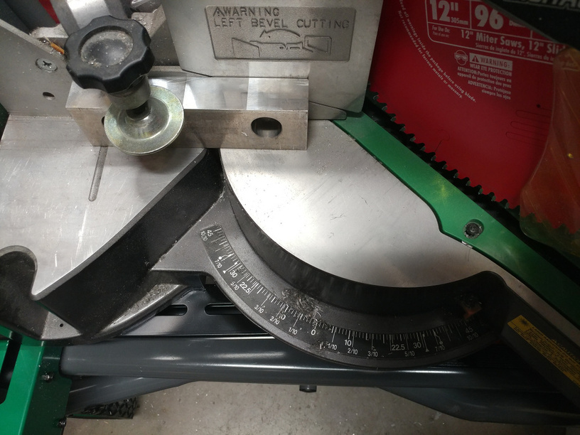
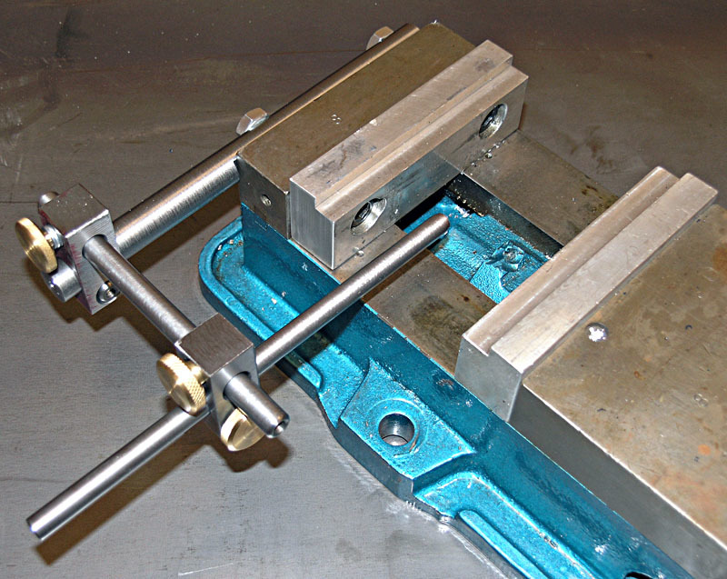
(image source: A Vise Stop for the Kurt Vise [ Easy Milling Vise Project ])
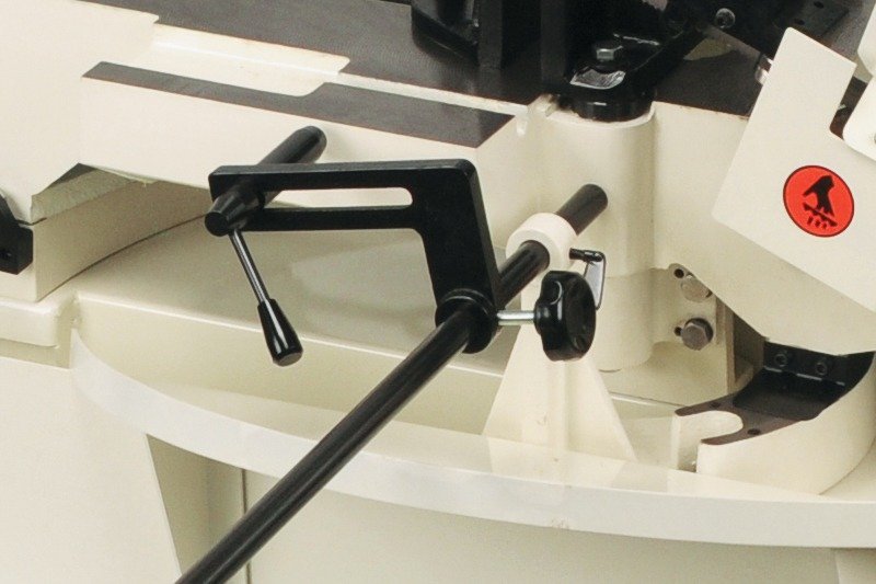
(image source: https://www.amazon.com/J-7020M-10-Inch-16-Inch-Horizontal-Mitering/dp/B003DB1GRY)
4 Likes
@karaelena @takitus
When you set your laser to 0,0, what is your tool pointed at? That is, what physical characteristic of the bed does it reference, that you can accurately laser-engrave your material without worrying that your material is a fraction of an inch offset or fraction of a degree rotated? In my experience on many other lasers, it references a random spot on the grate - nothing in particular - and then I have to put a mark there. If I ever want accuracy better than an eyeball, I do it by cutting a piece-shaped hole in material and then dropping the piece in there.
Would love to better understand your use case & existing solutions.
4 Likes
A use case would be wanting to laser pre-cut rectangular cork coasters. If you want to laser 20 off with the same image, having a known reference corner that you can just place the coaster against would be very useful.
Once placed in the corner, it would be great to just be able to hit the forge button for the previously aligned image to be placed in the same alignment on the coaster, with repeatability.
Having the reference corner would save making jigs and the issue of the jigs potentially moving.
3 Likes
Here are some solutions that I came up with that solves your issue…
Solution #1: Situate a piece of wood or acrylic about the length of the bed against the back wall of the Glowforge, then using Inkscape, Illistrator or a CAD program, I would cut out 5, 10 or even all 20 spaces for the coaster’s to fit into. Then I would iterate the engraved image appropriately.
Solution #2: In your base design use a “non engrave, non cut” color that is the size and shape of your coaster blank material. Then situate the image that you want to engrave with in the boundary. Then when you copy each image to your blank material just line up the bounding box with the edges of the material and adjust for rotation.
Solution #3: Use a larger piece of material for your coaster’s base, Cut each item out of it. In your cut file arrange all of your cut and engrave pieces in such a way to maximize material usage and minimize waste. This way when the material is placed on the bed all you would need to do would be to move/rotate the image OR the material minimally to get optimal alignment.
Overall: The bonuses of the camera alignment system of the Glowforge is that a 0.0 point is not necessary since you can manually align the project onto the material it’s self. This fact is also what has me personally MOST excited about the Glowforge. 
3 Likes
I’m going to take a wild guess at the alignment methodology. A great deal of brain power has been spent worrying about head positional knowledge and whether a particular use case is built in.
I’m guessing here…the GF doesn’t have a startup 0,0 or anything more than a rough idea of where the head is initially. It probably only knows a rough stow position so that the head can move in a proper direction after startup. The overhead camera determines a fairly accurate head position after startup. But there will be some slop in this position. This 0,0 accuracy is limited by the resolution of the overhead camera. It is independent of the internal honeycomb or any other physical mark. It may be slightly different for each and every GF unit. Do not confuse the high accuracy placement of the laser spot after 0,0 has been determined with the lesser accuracy of the initial position. 99.5% of us don’t care if initial 0,0 is off by 0.001" or 0.1". We visually align the design with the material. The digital image from the cameras will aid that process through position and zoom capabilities. For those that believe they need a predetermined unchanging 0,0 at startup I think in real world operations you will find the GF methodology to be different, but more than OK. For most of us the GF method will be far more user friendly.
4 Likes
I’ve more or less decided to adopt a “wait and see” attitude. 
Whatever the machine does might be better than having a single origin. A single 0,0 point origin didn’t do anything as far as rotation went, and it was ridiculously easy to get a cut slightly out of skew when we tried to do PnC alignments with some of the digital cutters.
We would probably need to figure out some way to get a 3 point Registration system going, to use with the camera, but I can’t for the life of me figure out how you could do that consistently with something that isn’t printed, and a standard shape like a sheet of paper or a rectangle. (I always circle back to needing a physical jig of some sort, be it paper, cardboard or wood.)
I have faith that the folks here are clever enough to figure out a way to make it work until GF can look into something like 3-Point Registration though, and I plan to experiment with it after I receive the laser and can see what it does, and what the limitations are.
(The suggestion to look into 3-Pt Reg is in the hopper from way back…I put it up for grabs shortly after joining the forum, and there have been several subsequent discussions on the origin, so they do know that some people are interested in seeing it added to the functionality.)
They’ll have time to look into it for the next round, after they have all of their current commitments shipped out, and by then we can see if it’s even necessary…we might decide it’s not a big enough deal to mess with. 
Maybe a few people will be given the opportunity to volunteer to beta test the upgrades before they release them. (That way those who want the functionality can make sure it meets their needs.)
Anyhoo…a bit too soon to worry about it. I haven’t seen how this one will work yet. That comes first. 
4 Likes
The questions of “is there an origin point” and “are there stops” shouldn’t be able to be turned into a 70-post thread.
We’re like Glowforge speculators here, trading theories about an object that already exists.
The answer to these questions could be as simple as "yes, and here’s a photo of them…
"
Or the answer could be “The origin point is generated each time the laser is powered up, so once you turn off the laser the origin point is lost. There are no physical stops and no provisions to add them.”.
10 Likes
I thought (although I could well be mistaken) that there was some discussion of the head-mounted camera being used to find 0,0 by looking for some logo or other (remember, you don’t have to find 0,0 in particular, just n,m). But a back of the envelope for the overhead camera suggests that position should be repeatable on the same machine to something like 0.01 inch without fancy subpixel analysis. Which is not great, but pretty good.
2 Likes
Pretty sure it’s the overhead camera looking at the Glowforge Logo on top of the flying head to determine the initial X, Y location.
3 Likes
Yeah, I remember that being mentioned somewhere as well.
Just waiting to see how it works.
Agree
2 Likes
My machine has hard limits, and when it homes it goes to the hard limit first, then moves the specified distance to the soft limit (35mm on the X). When I first got the machine I put a corner piece that runs along the edge of the soft limit and attached it so that I always know where my 0,0 is and can align pieces against it.
I havent had any issue in creating parts that fit flushly with others Ive cut on my CNC machine, and can easily queue up another to be cut without worry. I just shove the piece into the corner, then cut. On a number of those I do have to manually input the offset of the cut from 0,0 to get the cut where I want it to be, but I know that it can always hit it reliably.
Numeric positioning also helps me a lot when making sure I make the most of my materials. As different materials have different kerfs, I know what the minimum distance I can place and object away from another and still achieve a clean edge while maximizing the material usage. It may sound trivial, but there have definitely been times where an extra half a milllimeter has been the difference between being able to make the part now vs having to order another piece of material and waiting for it to arrive.
7 Likes
@dan, I think the question has still not been clearly answered. [quote=“dan, post:68, topic:3386”]
If I ever want accuracy better than an eyeball, I do it by cutting a piece-shaped hole in material and then dropping the piece in there.
[/quote]
Again, where do you ‘drop’ it? Do you just prop it against the enclosure walls?
Let’s try put it another way. The GF working area is predefined at 500x300. That should not be a variable. It should have pre-defined XY limits. How do we know where this envelope is on the bed? Trial and error?
Please clarify this for us.
3 Likes
We’ve gone around and around on this, so I must not be explaining it very well. I apologize.
Can you explain what you’d like to do, and how you’d do it on whatever system you’re used to? That might help me explain better.
@takitus: [quote=“takitus, post:78, topic:3386”]
When I first got the machine I put a corner piece that runs along the edge of the soft limit and attached it so that I always know where my 0,0 is and can align pieces against it.
[/quote]
You can do this with your Glowforge. Make that corner piece a little oversized and laser-cuttable, position it in the top left, then cut a square in the top leftmost corner. It will be aligned with the laser’s top-leftmost range of motion.
16 Likes
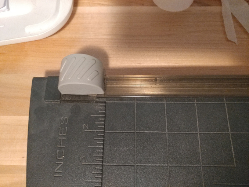
I think it’s as clear as it can be. (photo credit to @jacobturner)
Shove a piece of cheap wood in that corner. Cut an “L” or, as you say, a square in that corner by dropping a design in. Default position, from what I can gather, is the top left corner. Right? Could be tape or whatever if you wanted.
11 Likes