In the hopper!
5 Likes
Could you explain the inaccuracies and inefficiencies that G-code can cause a bit more and how current versions of the software get around that?
1 Like
I wish I could dump all my likes on that. Means we could engrave the honey comb into the bottom of an L shaped piece and use that as a jig for any item ever we want specific placement on!
3 Likes
Not dan, but in playing with 3D printers and baby lasers and machining I’ve run into some of the problems with G-code (or at least with common G-code interpreters). One big one is that it’s neither reliably serial nor reliably parallel. Some actions block, others don’t. (For example, you have to decide whether to set your hot-end temp to XXX degrees and pause everything else until it gets there, or to set the temp, not pause, and run the risk that some subsequent operations will fail because you haven’t reached temp yet.) And it’s underspecified: if you say “go from this point to that point at this speed” your motion planner will make its best effort to do that, but it can’t really promise how fast you’ll be going at any of the points along the way. So you end up either dividing things into tiny little segments or else having a motion planner that also adjusts you extrusion/cutting/whatever rate behind the G-code interpreter’s back to get the results you want. (The “proper” gcode for a raster engrave, as far as I can figure it out, would be pretty much one command per segment of light or dark space, hoping that no motion-planner bug would mess things up. Instead of “move from here to there at constant speed, and meanwhile send this waveform to the laser”.)
G-code is a very useful lowest common denominator, but for any specific machine it’s a less than ideal solution.
Well, G-code has worked just fine on my CNC mill and lathe so I was wondering what @dan was getting at and am hoping he will reply at some point as he is the only one that can say what he meant.
1 Like
It’s an intermediate approximation that doesn’t add any value on our server, and creates rounding errors (at best) and inaccuracies and data bloat (at worst). Like translating from english to polish to swahili when your goal is to go from english to swahili.
I’m not the expert here, but if memory serves all the 3D engraving code wasn’t possible until we rewrote everything to directly map the greyscale image to motor and laser instructions, allowing the laser to change faster than the motor could react.
10 Likes
Exactly this, thank you.
3 Likes
One difference between mills and lasers is that our laser can turn on and off a thousand times a second, so the output is capable of much higher resolution - if the input format can support it.
6 Likes
I’m trying to parse this from the context of a CNC mill that can move in 3 axes at speeds approximating 1,000 ipm at a resolution of 0.0001-in in location but maybe its an apples and oranges thing, so should just drop this as one more mystery of the universe.
Does anyone know if high end lasers from Trotec and their ilk use G-code or an approach that is similar to Glowforges?
Apologies, didn’t mean “lasers are faster than mills”. Just that mills are designed to move between points, very precisely, doing pretty much the same thing along the way, and G-code is optimized for that (although other modes of operation are possible). Lasers benefit from a different approach reflecting their own strengths and weaknesses - simpler motion but much more complex on-and-off-and-partway-on behavior.
8 Likes
No need to apologize - I was mostly thinking out loud and no negativity was intended. Kudos on the Q&A, BTW. You sure are good at rallying the faithful. I mean that in a positive way.
4 Likes
Head accurate and consistent zero position. Understood.
I can place fixture in bed (consistent and accurate). Understood.
Software that lets me numerically (x,y) position the image to cut relative to the head zero. Not answered.
I don’t want any community answers.
2 Likes
No, you can’t enter a numerical offset right now.
3 Likes
Thank you. We need to be able to locate the drawing to be cut to a software repeatable location relative to the head position.
Please add a numeric 0,0 in software interface at the cut head origin, or an alternate way to snap the drawing zero to the head zero point.
I appreciate your timely response.
1 Like
If you make an SVG, can you rely on the positions in the SVG file as being repeatable with respect to the machine’s home position? Everything I’ve read leads me to think that the answer is yes, but I might be missing something.
2 Likes
@marmak3261 and/or @dan
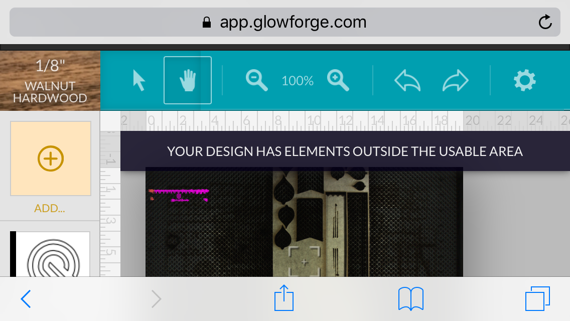
It appears from the upload of interface that marmak3261 provided that there is a scale showing the bounds of the electronic interface and cutting area inside the machine.
- is the scale shown on the interface tied to the head zero position (and consequentially to a fixed offset for the actual machine (0,0) position inside the machine… presumably (-10,5.25) from the head (0,0) based on a working area of 20x10.5 )?
- when importing the drawing file, can you “snap” the outside edges of the cut/engrave file to the 0,0 edge as shown in the interface. (see below)
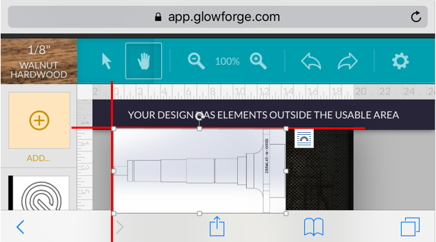
This would presumably then give you precise registration of the file to a known precision location on the bed. If there is only an “optical” alignment of the drawing with lid camera or trying to look at the scales on the sides to eyeball the file alignment, there is no precision for the cut file to the part in bed.
marmak3261 was showing how the file could “hang” over the edge and show elements outside of usable area.
2 Likes
Good question: I have not paid attention to them since I have been zooming in and placing according to where I want it to cut on the wood. I have to say that I am really having a hard time appreciating the 0,0 X,Y issue, not having had a machine where this is critical. I know it is a critical part of most of people’s workflow.
I’m doing one off piece where I want to maximize utilization of the wood I have. I’ll keep listening and watching.
Perhaps when I line up all those almonds in a jig! 
6 Likes
If you want I can send you my M&M engraving jig file. It holds 25 plain M&Ms for engraving. Mine is acrylic so I can wash it if needed.
Make one from the 0,0 position, do a whole bunch of other stuff and then make another from the 0,0 and see if they are the same. Or just save the original piece of acrylic, slip a piece of cardboard under it, put both in the GF against the 0,0 and see if it cuts the cardboard to match the hole that’s in the acrylic from the original jig. I can send you a piece of acrylic and chipboard for the experiment.
4 Likes
I think it’s useful if you cut a piece, engraved things on it, like your company logo. And then you went off, did a bunch of other random things with your 'forge, then then decided… “Ya know, instead of engraving our company logo, I want to make it an inlay.” Could you take that piece that you’d made a while back, target your existing engraving of your logo, and now make it deep enough for your inlay?
Basically, doing a second pass on the exact same spot.
Just a question. If you get no time to test/answer it, you’ll just go straight to he… I mean, you’re still awesome and it won’t affect my good thoughts of you or purchase in any way! 
1 Like