Cut artwork exactly at origin?

Hi,

Just wondering why the GFUI prevents a job from printing if the artwork is exactly at the origin? It says “No artwork” in the top-right corner of the GFUI but if I nudge it slightly down/right then it switches to “Ready” and prints fine. Equivalently if I upload a new SVG with everything shifted 0.5mm then it’s fine also. (But didn’t work if I shifted less than that).

This seems like a minor but fairly unnecessary limitation? (And hopefully easy to fix! :smiley: )

Thanks!
Jim

Jim, I don’t think we’ve seen the fullest potential of the size we can cut at this time. However, it also depends on what you’re doing. The motion planner has to take the speed and power of the cut into account when planning. There has to be time to decelerate. So in many cases you can’t go right to the edge because that doesn’t leave any room to decelerate… depending on the speed the head’s traveling.

Thanks Tom – I should have clarified, by “origin” I mean what the GFUI calls 0,0. This is still well off the bounds of the gantry’s range of movement (or even the crumb tray). And for the sake of half a millimetre, it seems like an odd restriction.

Well, very specifically, the GFUI doesn’t call anything 0,0. If you’re talking about the starting point of the head after calibration, that’s out of bounds. I believe that’s primarily due to the camera’s abilities.

I’m not sure I follow. The GFUI absolutely has a notion of 0,0 – there’s a ruler along the side!

I’m not talking about the starting point of the head after calibration (which is about 20mm to the left of where a print at 0,0 would appear).

I’d love to know more about exactly how that calibration process works? Surely the camera isn’t used for homing, that sounds like a job for limit switches or similar! (Which camera, lid or head?)

FWIW, however it works, 0,0 appears to be a repeatable enough location that it’s a convenient place to align work to so that I can be sure that I don’t accidentally miss the edge of a cut or something due to the camera being off.

2 Likes

Yes, the lid camera is used to determine the location of the head through the logo on top during calibration. It then just simply counts the motor steps to park at the home point in the upper left. No limit switches.

I’m not going to get into it, but it doesn’t. For your enjoyment:

Purely a visual aid for human operators.

Yes… The lid camera is used for homing.

1 Like

I have had the same issue the reason is that the artwork is not within the cutting area. Once the artwork is within the area then it will show up as ready…

OK thanks for the thread, that was a long read, and some good info but I’m not sure it really got to the bottom of it. There are really clear statements from @dan and @Tony that seem to suggest the following:

  • The head is calibrated using the lid camera and this is sub-millimeter repeatable. See XY home position
  • SVG coordinates are repeatable over time. See XY home position

But then contradicted by:

  • “It does not appear that way in the UI”? See XY home position
  • “what is being discussed as “0,0” - that is, the northwest most addressible corner - will change with the speed you use.” XY home position

So can someone please nail down the inconsistencies between the first two bullet points and the second two? There are seemingly six different explanations of what 0,0 is:

A: The absolute travel bounds of the gantry
B: The position of the head after calibration
C: The north/west most addressible point (i.e. the north/west most point that can be cut/engraved/lasered)
D: The 0,0 coordinate of the SVG file that I have uploaded
E: The 0,0 coordinate of the rulers in the GFUI
F: The places that D (and E) end up in on the final print

Importantly: A, B and F are physical coordinates, D and E are entirely logical. C is kind of both. Also, I understand why there’s no physical ruler on the GF itself - B is at best relative to the lid camera, but certainly not to any other part of the machine and definitely not the crumb tray.

  • I can definitely verify that D and E are the same thing (when I upload an SVG vector that’s at 0,0 in the SVG file, it gets placed at 0,0 on the rulers).
  • A isn’t terribly important other than to understand that it’s not the same as the others.
  • B is calculated using the camera and is repeatable across time. i.e. it’s likely to be sub-millimeter the same physical position. This seems fairly unambiguous in the thread.
  • C is print-dependent (i.e. speed and deceleration factor into this) (and operation dependent within one print)

So the question is: Is the relationship between D (and E) and F:

  1. Completely meaningless (:scream:)
  2. Print-dependent (i.e. F is based on C). (this would be understandable but :cry:)
    2.1. Different for every job, deterministic but competely unpredictable by the user.
    2.2. Most jobs will be a fixed offset, but jobs requiring more “difficult” movement will sometimes cause this to be different.
  3. F is a fixed offset from B (hooray! :partying_face:)
    3.1 C is always above/left of F no matter what is printing. (Woohoo! :partying_face: :partying_face: )
    3.2 C may be inside F. i.e. sometimes I am prevented at cutting at 0,0 because of the artwork that I have placed there. (That’s cool, if the GFUI makes this clear)
  4. Something else? (:confounded:)

(Edit to add 2.1 / 2.2 and 3.1 / 3.2 as two possible variations of 2 & 3).

@Tom_A it sounds like you’re saying it’s (2). This appears to be contradictory to my understanding of this post from @Tony. Additionally it goes against my reading of this post from @dan unless there’s a very subtle clarification required that he means “the same SVG file” (and the same operations from that SVG file).

Glowforge - can you please write this up somewhere easier to find than the forums?

All that said… I still don’t understand why I can’t place my artwork at 0,0 but 0.5,0.5 is fine.

Thanks

2 Likes

Quantum answer (semi seriously) 1,2 and 4. :grimacing:

Your post took a second to parse, you went deep!

I think you may have gone a bit deeper than necessary though – My understanding and experience is that 0,0 in your SVG is repeatable, but whether or not that is in the printable area_ depends on your settings. Engrave printable bounds definitely change based on speed, cut bounds seem to be consistent (though I haven’t verified that). That’s the simple answer.

Given that the tray moves and that the GF recalibrates on (at least) every startup, there’s no such thing as absolute 0,0 physically on the tray. In theory recalibration should be the same every time, but it might not be, so you shouldn’t count on it. That, in a nutshell, is why this question doesn’t really come up too much, because relying on absolute positioning in your SVG isn’t normally the best plan. Absolute position requirements (to within a kerf) are currently best met by using jigs, and jigs are all about relative placement.

Also, your software/assumptions might impact your notion of 0,0. In inkscape, 0,0 is southwest. That may not be the same for other programs, I don’t know.

So, tldr (too late), 2 is true and verifiable, 3 is almost certainly true, 4 is likely (but how would we know?), and 1 is a bit overstated – “meaningful but not explicitly made available to us” would be the way I’d have phrased it.

3 Likes

I use Cut2D (which I’m used to for CNC) - it lets you specify the origin. I’ve looked at the SVG file and there are no surprises there.

Good point that C may be inside or outside D – I’ve edited my question above to cover that. I’ve not seen that made obvious in the GFUI yet though.

How did you confirm that “2 is true and verifiable”? I figure I can do some test prints tomorrow to verify myself (by placing different speed / type jobs near 0, 0 (E)), but I’m not 100% how to do this in a way that’s exhaustive - any tips would be welcome. TBH I’ve barely played with engraving so maybe this will be super obvious when I try it. I also don’t understand how that can be the case if “3 is almost certainly true” – 2 & 3 have to be mutually exclusive.

2 is true because the print area shrinks down as you increase speed of engraving. This has been carefully experimented and documented elsewhere on the forum.

So yes the printable area depends on the job.

1 Like

You’re right that the print area available is restricted by the operation (e.g. engrave), but this isn’t (as far as I can tell) a reason why (2) is true. I’ve clarified what I mean by (C) above to address this. The print area restriction is applied differently to each layer – this does not change the 0,0 point (what I’m calling E). So while the print area for a given layer is decreased, what the GFUI calls 0,0 does not change.

This is easy to see in the GFUI – If I place an “engrave” artwork, then an exclusion zone appears, and the size of this exclusion zone is dependent on the engrave settings. Here are two screenshots showing the difference.

Note that in both of these screenshots, the small 20mm square in the top left is in the same place (0.5,0.5), and is allowed to be there (it’s unaffected by the engrave layers). And when I run this print, it works as expected.

This seems like everything that I can test points to (3.2) being the way it works. (And I’m happy! But would still love to get an official clarification!)

This is important! If it weren’t the case, then the jig techniques described here on the forum (e.g. many times by @Jules) wouldn’t work.

1 Like

Right, sorry. Your post is a bit hard to follow. 2 is true by itself but you combine it with all your alphabet points and you were asking is the origin moves, which I explicitly said wasn’t the case.

This thread requires a notebook to follow, you’re asking deep questions that I haven’t seen discussed before. I wonder if your software is the issue (in that the ui doesn’t understand its 0,0), you’re also the only cut2d user I’ve come across. Hope you get the answer you are looking for.

2 Likes

It’s correct that the print area shrinks down as you increase the speed of engraving, but the coordinate system remains the same.
Top left corner of an svg is still at 0,0 when using the GFUI rulers. No matter how small your engrave image is, you can never engrave at 0,0 since it’s not in the printable area.

I think and hope that it is 3.2.
My experience at least points me in that direction.

There has to be some physical point of reference, otherwise jigs would not work.
The head calibration would be the most logical choice in my opinion as long as it’s consistent and an offset can be used to virtually represent 0,0.

Back to the original question of why can’t we cut at 0,0 since it’s a virtual coordinate.
I’ve been wondering that myself and the only thing I can think of is the possibility of increased code complexity.

Somebody tagged me…

There are a couple years worth of discussion on the topic of origin setting. The Glowforge interface doesn’t rely on a fixed numeric origin. Instead, it relies on a relationship between the saved parts of a file to create alignment of the parts.

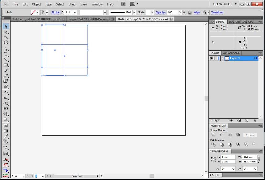
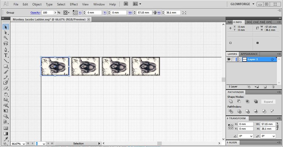
There is a work-around that you can use to open your cuts at the “origin”. Just set the artwork at the 0,0 point on your artboard in your design software.

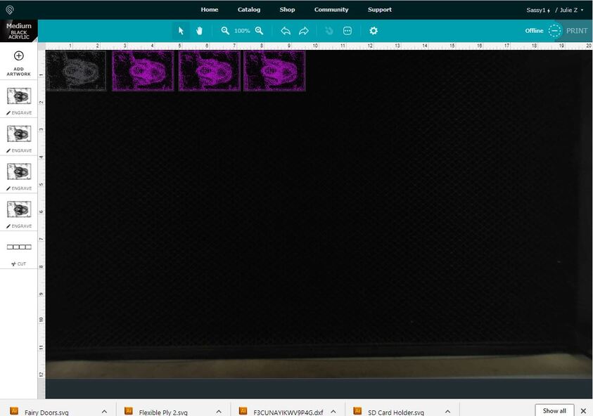
It will open at 0,0 in the glowforge interface.

That has absolutely no relationship to the point that it will be cut on the material though, because that can shift, but as long as that file is open, and if you can place the material in the exact same location that you placed it before, you can use it for numeric alignment.

(Generally doesn’t work out that way though, which is why cutting the jig at the same time as the engraving has worked better up to this point.)

That only works for cuts, not engraving, due to the varible no-cut zone on engraves. The engraves will snap to the 0,0 point, but you can’t engrave there.

You would have to determine the limit for the various speeds to determine where that point falls for each usage case. If you wanted to, you could then place the design at that point in your design software, and it will open in the same spot each time.

BUT…
Now, with the introduction of Snapmarks, they are using a form of fiducial mark recognition to align objects, and jigs are re-usable. So you can place them anywhere on chopped up sheets and the interface can search and find them, align the artwork, and get on down the road.

7 Likes

It’s been a little while since I’ve seen any replies on this thread so I’m going to close it. If you still need help with this please either start a new thread or email support@glowforge.com.

@jim.mussared: I’ve got a few things I’ll follow up with you in email shortly.

1 Like