When I cut thicker material it becomes obvious that the laser isn’t perpendicular to the bed. Instead, it points slightly to the rear of the unit. I haven’t measured the angle yet, but it’s noticeable. I’ve checked that the GF is level and the crumb tray is properly seated in the wells. I’ve removed and reinstalled the laser head. Is this common? Is there a fix?
Laser beams don’t actually cut straight up and down, there is a slant to the cut face profile any time you cut, and it is more pronounced on thicker materials. A laser beam makes an “X” with the crossing point of the X as the focal point. When that is placed on the surface of the material, the legs of the X will slant slightly as they cut through the material. You can change the profile of the cut face by focusing the beam into the center or bottom of the material, but it really widens the kerf. (Best to usually just leave it at the surface of the material unless you have something specific in mind for it.)
You can use that to your advantage when doing inlay work by flipping the inset piece before cutting it, so that the kerf profiles line up better.
Or if you want to shave it off a bit, run a second high speed/low power pass to trim it off a bit.
3 Likes
Exactly how much are we talking and how thick of material? Any visuals?
Have you re-seated the head on the carriage plate?
Very interested to see how you confirm this (support will need to know as it would require sending the machine back for re-calibration.) Certainly the first time anyone has reported this on the forum.
1 Like
A photo would help me understand the problem.
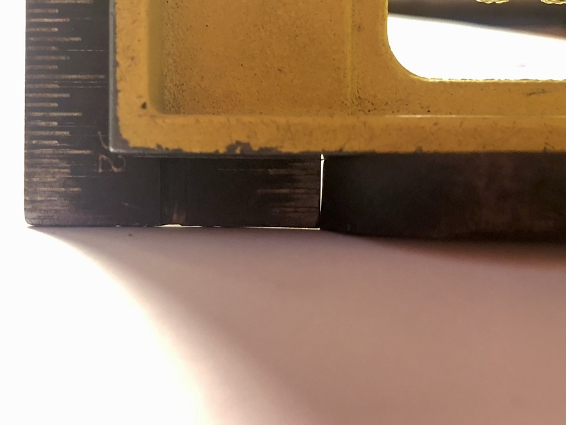
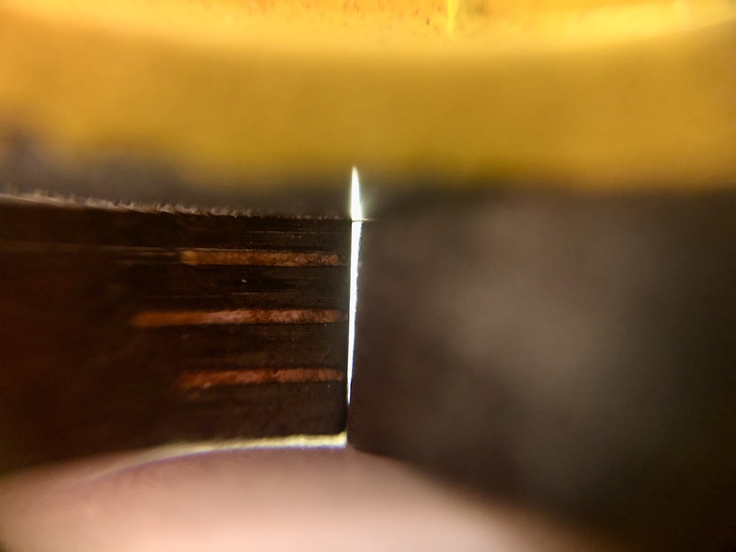
This is the best I could do. The material is 0.25" poplar from which I cut a circle. The picture is of the edge of the circle closest to the rear of the GF. The opposite edge is slanted the other way (i.e. the top surface overhangs the lower surface). It would be more noticeable on thicker material, but I didn’t have any. The laser was focused at 0.25" (the upper surface).
That’s exactly what @Jules was talking about above.
Most diagrams tend to exaggerate the slope, for illustrative purposes, I guess.
But, it’s more gentle. Like this.
10 Likes
Here’s a good topic that explores this and documents ways to determine if the cone shaped kerf is nominal or problematic.
2 Likes
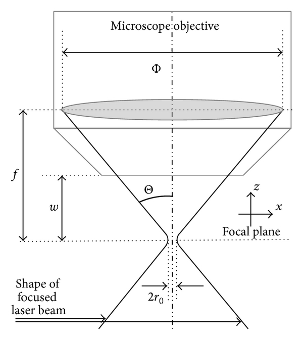
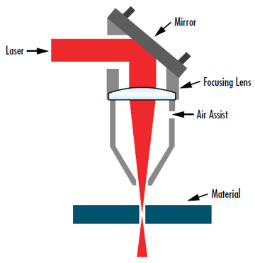
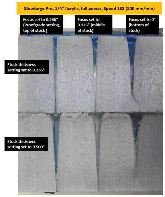
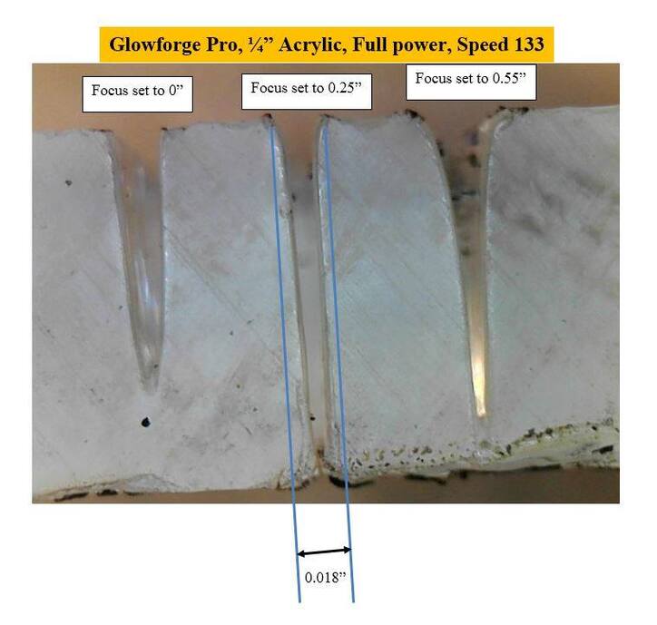
I forgot who made these helpful images so unfortunately I can’t credit them, but it’s a good look at the shape of a cut made by a laserbeam and how setting can effect it.
.
6 Likes
From your description, it sounds like it’s not the tapered cut, but the angle of the beam. I had not seen it, but the thread linked above has some great discussion and pics on this, but unfortunately the thread was closed without any resolution. @ben1 is a regular contributor, so perhaps they can provide more info. He had also re-seated the laser head several times and it made no difference.
1 Like
If you cut a small circle, is the slant consistent around the entire edge (that’s normal), or is there a lean towards one edge of the machine?
If the slant is asymmetrical, there’s something else afoot. Perhaps the head, perhaps the tray.
Do you have calipers? You can use the plunge to measure the depth from the edge of your tray to the bottom of the machine near the four corners.
If your tray isn’t seated properly it could have a slant.
2 Likes
My first laser was replaced due to the angle of the beam, as illustrated in the photos. The replacement is still angled slightly but not enough that I usually have a problem with it. I have learned that anytime I need a perfectly parallel/perpendicular slot I have to adjust the kerf slightly smaller and file the cut faces to the proper 90 degree angle. I am guessing that a lot more machines will show this behavior but most users don’t do projects with enough precision to notice it.
I did check my tray multiple times to ensure that it was not out of alignment and I also checked the flatness of the table I have the machine on to ensure that wasn’t a source of the issue.
2 Likes
Where do you think it comes from? My thought is the carriage plate on the gantry, which is why I suggested he re-seat the head first. No adjustment there, of course.
I wonder if a slip of thin paper or similar on one side or the other would work.
I don’t know where it comes from. I adjusted the angle of the head carriage by moving the rollers up and down and it didn’t seem to affect the angle. I figured it was just an angle in the carriage and spent about 3 hours adjusting and testing. I wasn’t able to make any correlation between the angle of the carriage and the angle of the beam, which is really confusing to me, considering it should be a simple solution. My angle was on all cuts in the X direction, so changing the angle of the head carrier should have resolved it. I don’t know enough about the internals of the laser head to be able to make any assumptions.
1 Like
Not even sure how you (actually GF staff) could measure that without performing cuts like you did.
Has me curious to try now, just 'cuz.
I assume it could be measured with a laser alignment setup, though I would have to think about it to see exactly how to measure it, but it can be measured.
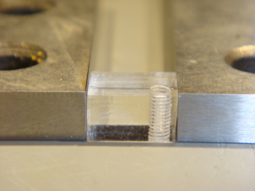
Sorry for the slow response. The slant is asymmetrical. In other words, I can’t rotate the circle 180° and reinsert it into the cutout. The above photo of the acrylic cube seems very similar to what I’m seeing. It’s skewed in one direction.
I’ve measure the distance from the top of the rail to the surface of the honeycomb at each corner as you suggested after making sure the feet and wells were clean:
LR: 2.825 RR: 2.835
LF: 2.824 RF: 2.844
That’s a maximum variation of 0.019 diagonally, but very little front to back which is the direction in which I have the issue.
The laser head unit, however, is not perpendicular to the surface. I just measured from the top of it to the honeycomb:
Front: 4.589
Rear: 4.608
That’s a difference of 0.019 over a very short distance. I think I can see a tilt just looking at it. It is properly seated. I’ve removed it and reinstalled with no change.
Hold on, just noticed something. The cross rail itself tilts slightly down at the front. I placed a steel straight edge flat on the surface of it and it drops about 0.110 from the back of the unit to the front, a distance of about 15”. I wonder if that’s normal?
1 Like
I doubt that is by design. I suspected the rollers on the carriage plate can be tuned to accomodate, but ben1 said he wasn’t able to adjust that out…
Thank you for reaching out about this and letting us know what troubleshooting you have already performed.
I see you have also emailed us and we are going to continue to work on this there, so I’m going to close this thread.