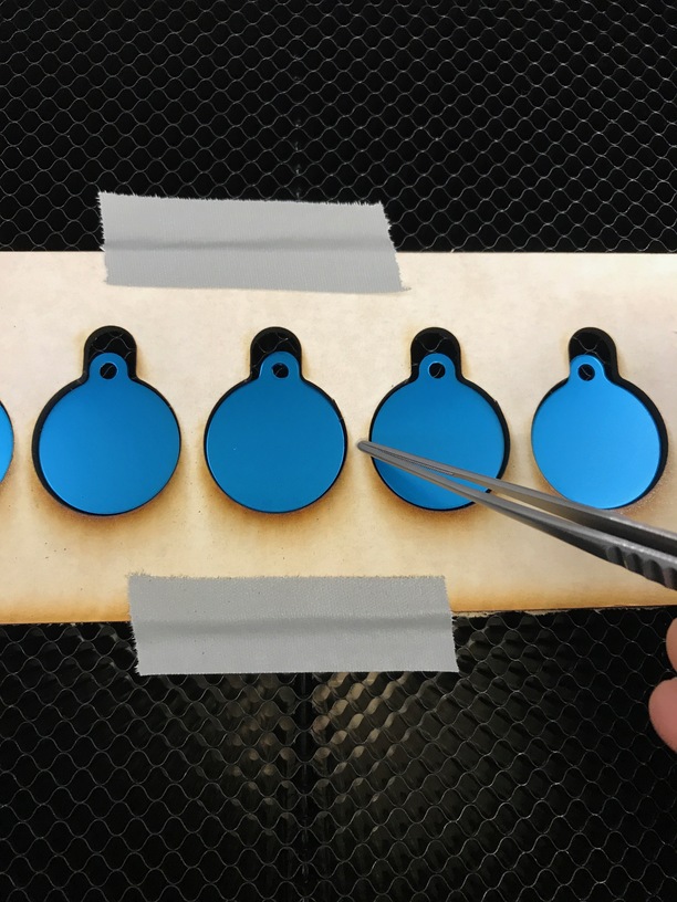
Ok, the setup is aluminum dog tags in a Drafboard jig. Since we have 2 Glowforges we can compare behavior. The first Glowforge (i.e. mine) works as expected. I click Set Focus and it deploys the laser where I expect (although not a huge fan of the new square, versus the old cross hair as the square is big) Anyway it correctly gets 0.2" height. And then lasing works perfectly. However on the other GF in the lab (XYK-336 under @Mike.Vet ) it selects the center of the dog tag (0.02") then when I fire off the job goes and selects a NEW spot (not on the tag). If you recall this GF (a Plus) had a fail I reported where it selected a random spot not on the tag before:
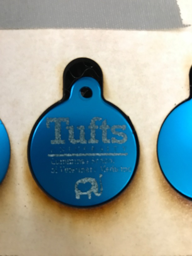
It also isn’t cutting through Proofgrade all the way, which I suspect is the same issue.
Troubleshooting, has been cleaning optics, rebooting GF.
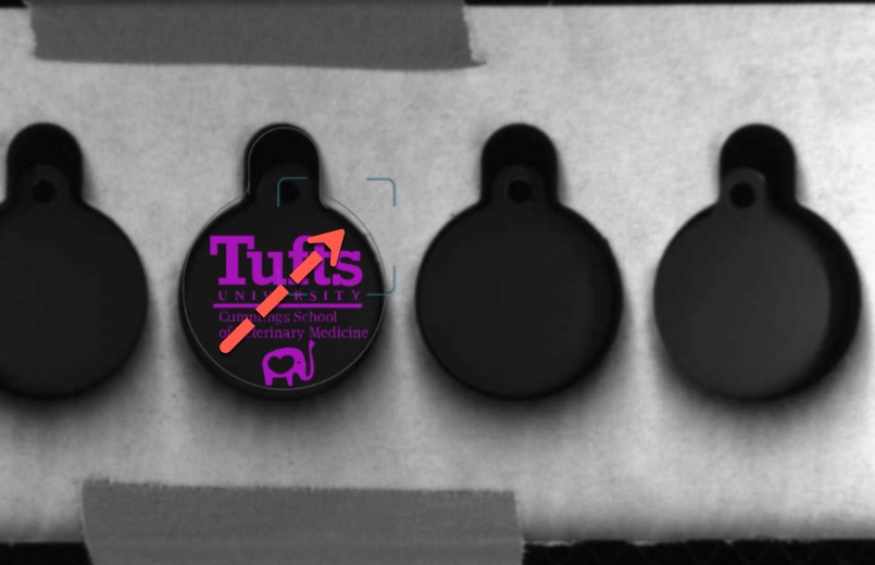
Also weird was I selected the tag center for focus, which it did, then when I started the engrave, it did this spot and of course selected half-tag and half-draftboard, which meant it had no idea of the material
BTW: In the photo which shows the focus half on the aluminum and half on the wood, that is not where I clicked (I clicked center of the aluminum), and the red laser did in fact scan the center of the tag, then the second time selected the location top right you see in the screen shot)
Watch to see where the red laser beam strikes. I’m noticing that it’s generally about 1/2 inch or so from where I select. In cases where that matters to me I try selecting again to compensate for the offset.
It might not help you, but I’ve just been noticing this over the past few days. Not saying it’s new behavior, just that I’m noticing it
Agree. Mine is significantly off center of the box even once the material height is locked in for the preview. For anything less than about an inch in size I would watch the red laser spot every time.
Dan used the word “approximate” to describe the box placement.
My take on @Dan’s explanation was that the square is big because the placement of the laser falls within a certain area around where you click, not necessarily that exact spot. I think the square shows that area. Then it leaves a smaller square showing you a little more precisely where it actually landed, so you can try again if it missed where you wanted it.
Just typed this in another thread… but, the area is approximate. The set focus box (and the crosshairs used before) are part of the design overlay, so subject to the same level of error that the design is subject to on an uncorrected image.
This is well over 0.5" in error. If only the laser had a precision motion system… Anyway on my home machine it pretty much nails it (or at least isn’t far enough off that I notice it).
Which is weird since they have the image correction (which nails it now with the new calibration tool). I now get sub-mm level accuracy, so not sure why they can’t use the same correction they already know…
Have been thinking about that. The position of the red laser spot may have an installation variance. After all it’s just a laser diode soldered on a circuit board. The spot position is not important as long as the head camera can see it. A factory calibration could take care of any installation error in S/W to ensure material height accuracy. But the actual spot position is not S/W adjustable. It is H/W fixed.
The fact that it’s fixed and points straight down, to me, is what’s supposed to make it supper-accurate. I don’t get why on Earth it would need to be an approximation. It’s a calibrated head at that point. It knows where the red laser is in relation to everything else. It just doesn’t make sense to me.
I get that it might be a “smidge” off as it’s placement on the circuit board might vary by a tiny amount, but even there we are likely talking fractions of a mm. I mean being off 0.5" is silly. And again, my home one is practically dead on, so not sure why it needs to be like this. And obviously easy for the factory to calibrate a spot to the laser diode. I mean you have 2 downward facing lasers, which is sort of the definition of things you can measure…
It doesn’t point straight down. It points at a 45 degree angle which gives an elongated spot. The length of that spot, not location, is how material height is determined. The spot location is in a completely different place for a height of zero than a height of 0.5" due to the angled projection…
Actually, I was typing tired and those words were not what was trying to say. The left/right position within the head camera image of the spot edge would determine the material height. Because it’s at an angle, as you raise and lower the material the spot will move left or right. I was intending to clarify between how lasers are most often used to measure distance directly and how it’s done in the GF with the angular method. Sorry, I mistyped.
Because the only way that can work (especially in a slanted version where you get the hypotenuse and are calculating the sides) is if you know the basic geometry of the origin. Since they have to determine the height to hundredths of an inch, seems like X,Y is critical…
I tend to think that being off 1/2" is not unusual and possibly even the norm. My measurement is taken 1/2" off the center of the Set Focus Marker even after the material height has been determined and the Preview image is perfect. If you are interested in reading how I tested it and seeing the pics…