Notice to new owners looking for instructions on how to use the Passthrough:
Glowforge has now developed their Passthrough software and it is much easier to use than the method described below.
The link to the Glowforge tutorials for using their Pro Passthrough software can be found here:
Using Inkscape with the Passthrough
I got a private message for some assistance in creating a file for Passthrough use in Inkscape.
(A caveat up front, I’m not an Inkscape expert and there might be an easier way to do this, but the overall process works the same as the process for Illustrator, so I’m going to capture the steps here in case anyone else is having trouble figuring out the sequence of events in the design. The cut process is very labor intensive in Inkscape.)
Part One: Create your Design
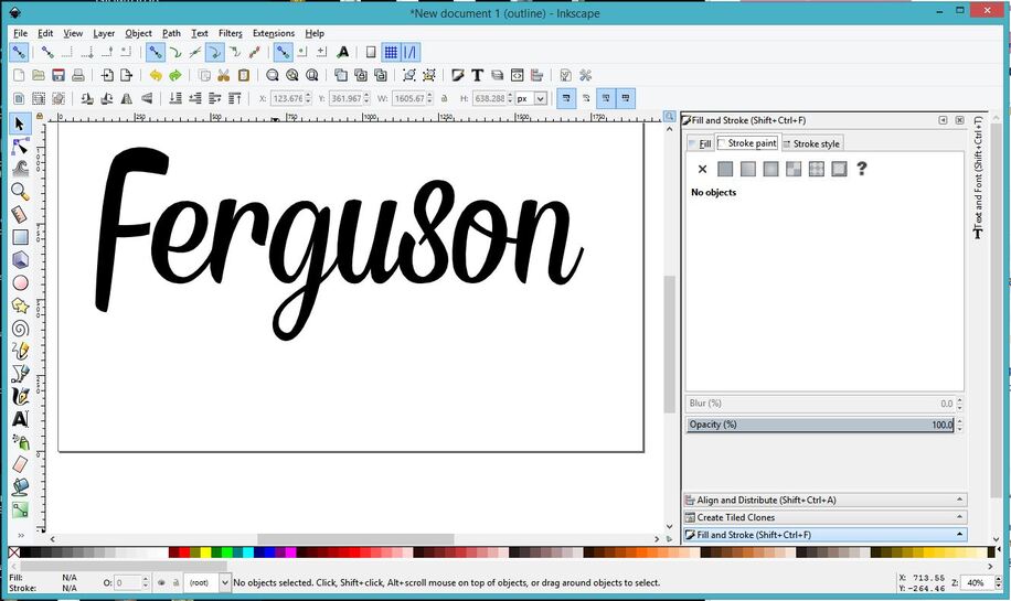
1. Open a new file (20" x 12") in Inkscape.
2. Type the text really large in whichever font you want to use. (You can size it later.)
3. Select the text and click Path > Object to Path
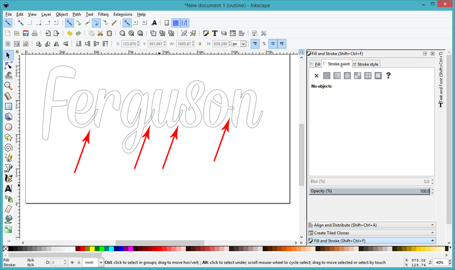
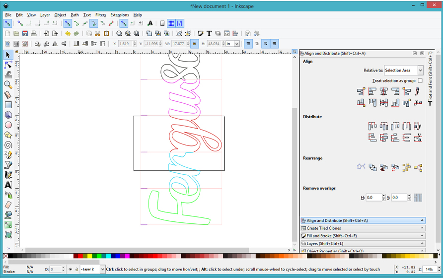
In order to see what just happened, (because it’s going to look like nothing happened when you do that), you can set the mode to Outline display mode…it shows the actual shape of the letters without displaying the Fill color. Fill color in text tends to obscure overlaps. The Fill is still there, you just don’t see it in Outline Mode.
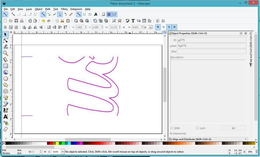
Click View > Display Mode > Outline
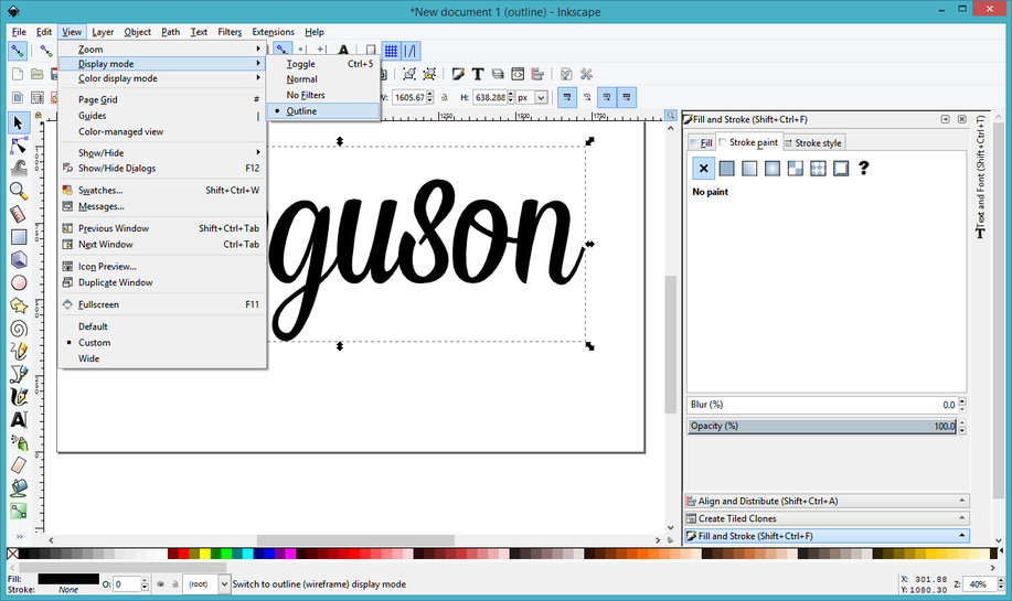
And you get this:
See where the individual letters are not joined? They overlap each other and will cut as independent letters. They have to first be joined into one overall shape.
4. Those are grouped together, so right click and Ungroup. After Ungrouping, shift the letters over so that they overlap everywhere you want them to. (If they’re not joined together, you will get separate parts of the word.)
5. Now you want to join them, and since they are ungrouped, you can merge the shapes together using Path > Union.
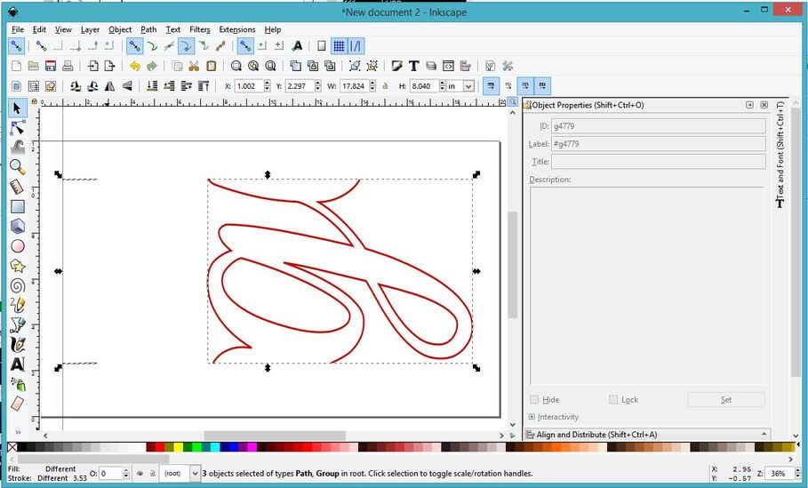
You can see where the individual letters have joined into one shape.
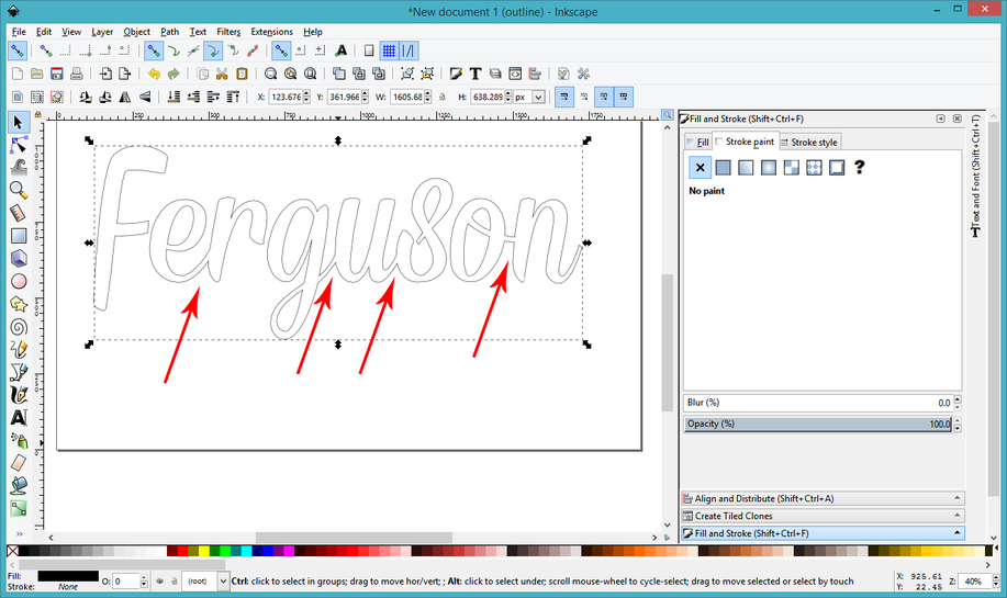
6. When you’re done merging the name together, you can go back to Normal viewing mode. You will see the shape looks exactly how you left it. At this point, you need to set the Fill color to null, and give it a Stroke color. That’s how you set up a file to cut.
Part Two: Preparing the File for Passthrough work.
1. Scale your file so that the Name measures the correct size. In this case the desired overall dimension was 48" long, so select it, lock it to scale it equally, and set the measurment for the width to 48 inches.
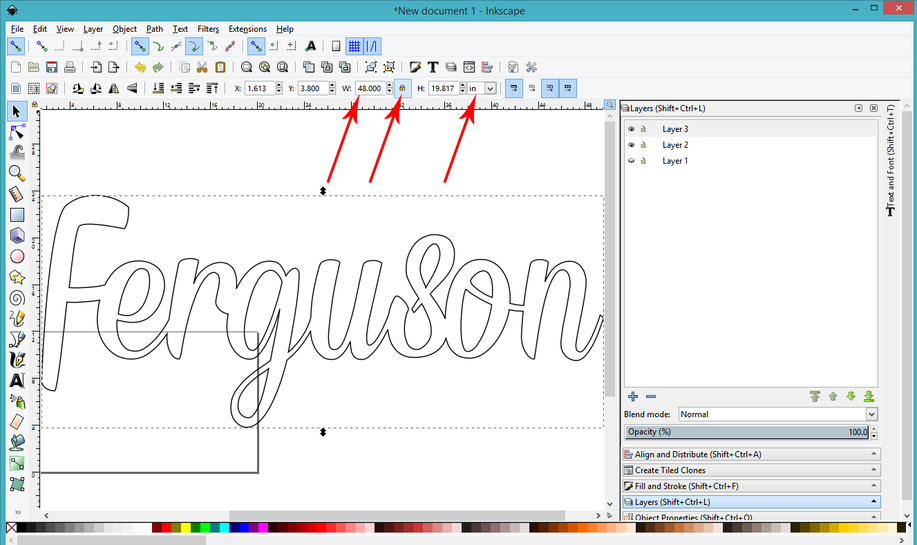
(Very important note: Make sure the height of your word overall is not larger than about 18 inches. You need a little bit of leeway for the marks and the jig alongside it. If necessary adjust the height down without impacting the width. Cutting your material down to 20 inches or less helps a lot with alignment and pinning.)
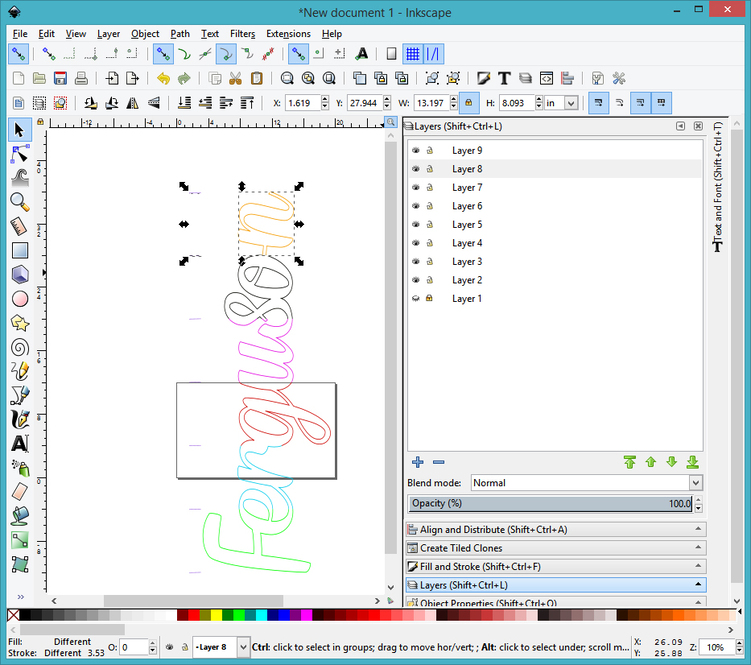
2. Now you’re going to shift the file onto a new Layer, so you can insert the cutting guidelines underneath the name.
First create a couple of new layers in the Layers palette by opening the Layers palette and clicking the Plus sign a few times. That adds layers to the design.
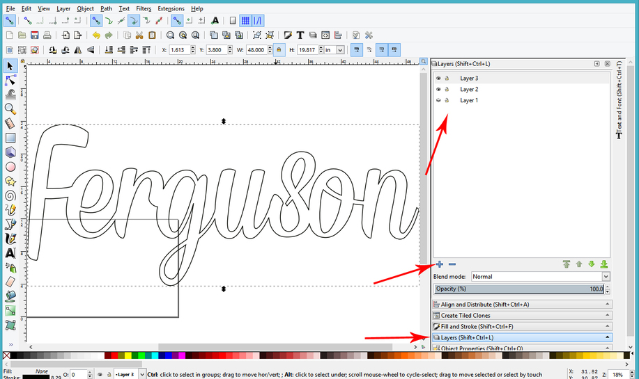
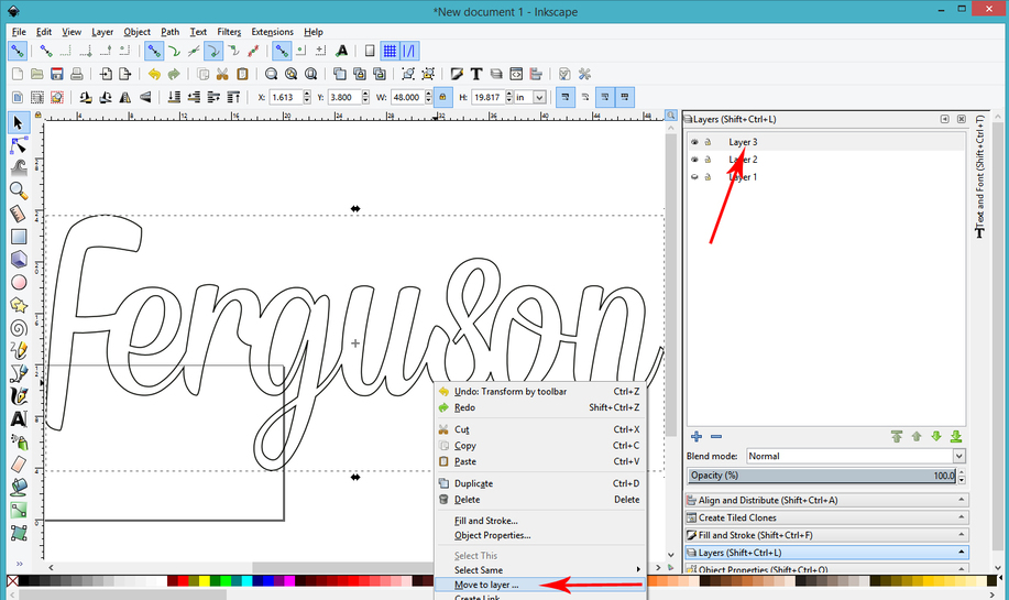
Shift the name to the top layer, by right clicking on it, choose Move to Layer and then choose the top Layer. (Layer 3 in this example.)
3. Save a copy of the file at this point. Give it a new name. (File > Save As > New Name)
(This is a copy of your original, in case you want to change something later. Trust me, it’s gonna happen. Save a copy.)
Now you’re going to start creating the passthrough files. You will create separate files for each of the split sections, it’s just easier to keep track of, than jumbling everything together.
Part Three: Creating a Passthrough Master File.
1. Create a Guide to use when cutting the file.
There might be an easier way to do this…if so…do it. I’m not real proficient in Inkscape. ![]()
Update: And of course there is…read on down a bit to this post…Marmak3261’s Method
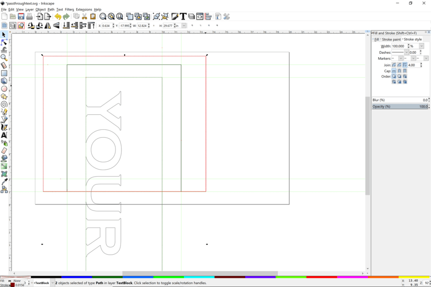
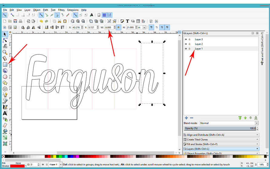
Since this shape is 48 inches long, and it needs to be split up into sections that are less than ten inches, I chose to split it into six sections that are 8" wide. Easiest way I know of to do that is to create one rectangle exactly 8 inches wide, then copy and paste it to create sections.
Click on Layer 1 in the Layers palette, then drag out a rectangle and set the size to 8 inches wide. Give it a red stroke just for kicks.
After creating the rectangle, you can copy (CTRL+C) and paste (CTRL+V) it five times, then align the corners of the rectangles together to create a grid behind the word.
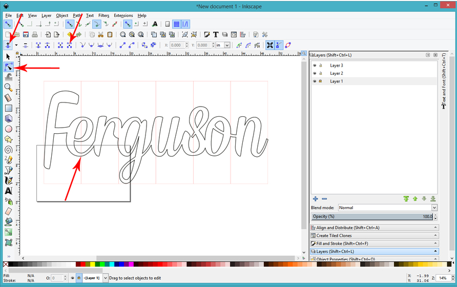
Last step here is to Lock the red grid. Click the little lock icon on Layer 1 in the Layers palette.
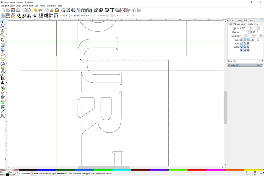
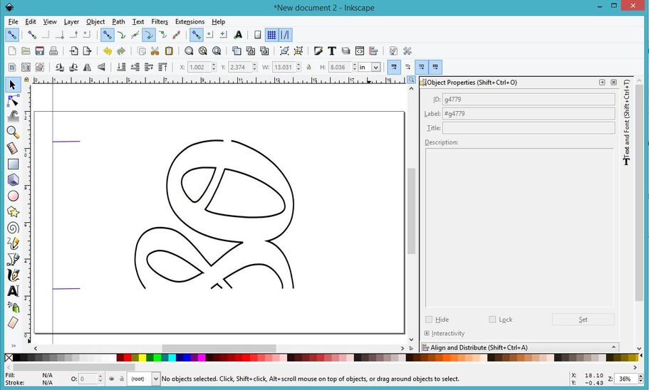
2. Cut the word every where the black word crosses a red line. This is not the easiest thing to do in Inkscape, since it relies on node editing and will continually try to close the path. The steps are:
- Select your design objects and Convert to Paths. (If you have not already done so.)
(Path> Object to Path.) - Enter the Edit mode.
(Click the Edit Paths by Nodes arrow or F2). - Insert new Nodes into the path segments where they intersect the Guide.
(Double click on the path after clicking the Insert Node at a Point tool.) - Break the path at the newly inserted nodes.
(Select the node, click the Break Path at Selected Node tool.) - Break Apart the design.
(Select the parts > click on Path > Break Apart.)
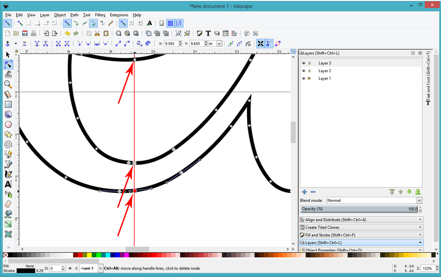
The bad news is, sometimes you will have to cut and Break Apart the paths multiple times, it’s difficult to know how the program is grouping and creating Compound Paths out of the text. Keep breaking at the nodes and Breaking Apart the paths until they are actually separated.
You can tell they are separated by looking at the bounding boxes for each section when you click to select the various parts.
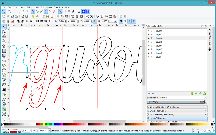
(At this point, as soon as I get a section completely separated, I like to change the Stroke color and shift it to a different Layer for ease in handling. The color change will eventually be necessary, the Layer shift is not…it’s just up to you how you want to handle it. It’s easier to grab everything on one Layer when all other layers are temporarily locked down, so I’ll usually insert a few more Layers at this point.)
3. After you have completely cut through the paths at the grid lines, select all of the path segments inside of a particular section and give it a different color Stroke. (Since the red grid lines in the bottom Layer are locked down, you can just drag across them to capture all of the segments inside each section.) The colors you choose do not matter, you just want each to be a different color.
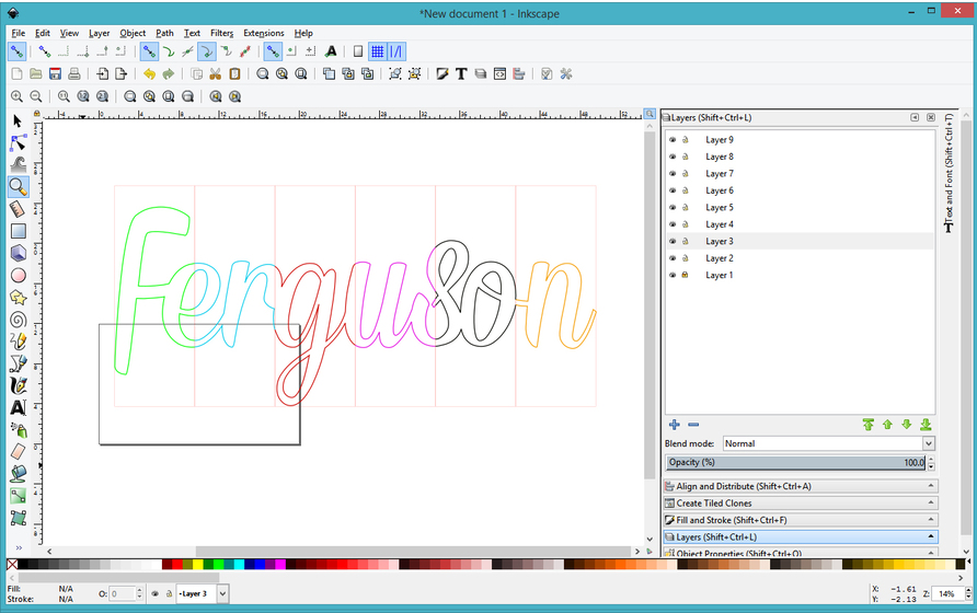
4. Group Like colors together.
(Click on a line, click Edit > Select Same > Stroke Color then CTRL+G to group.
5. Unlock Layer 1.
6. Select all of the color groups and the red grid and group it. CTRL + G.
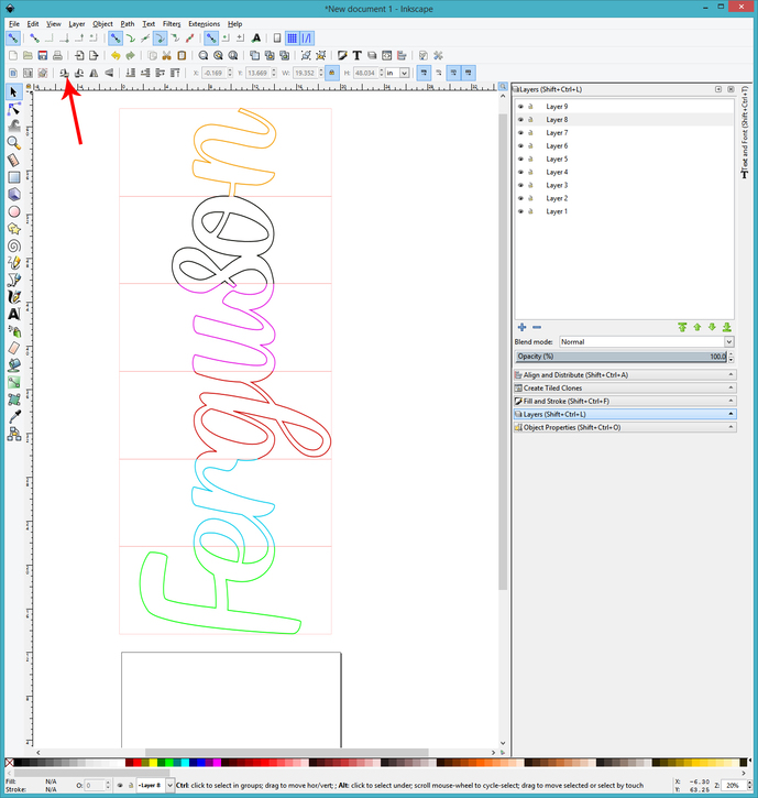
7. Rotate both the color groups and the red grid counter-clockwise. (This is how the sections will feed into the machine, and you can see the bed size underneath the word below. Make sure it’s going to fit as it is processed through. If it’s too wide to fit, squish the width of the group at this time.) Ungroup the grid from the word when you’ve checked and adjusted the size, then lock the grid layer again.
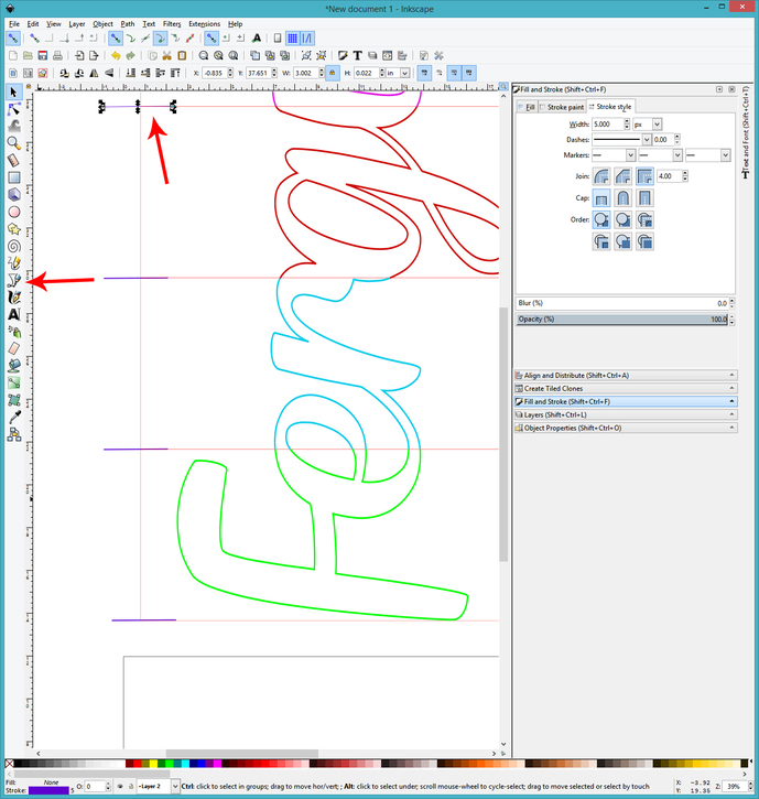
8. Create the index marks for the file.
Click the Bezier Tool, give the Stroke a different color than all the other colors, and drag out a short horizontal line. Make it nice and thick so you can see it, the stroke width doesn’t matter with vectors, the cut is always the same thickness.
After you create the index line segment, copy it (CTRL+C) and paste it (CTRL+V) several times and align one mark at each intersection on the grid. (You can put them on either the left or the right side, depending on which side you prefer to anchor off of. I like to use the right side, more of the cutting area on the bed is displayed. In this case, I’m showing on the left side since the word pretty much fills up the entire cutting area of the bed. Each of those marks should be exactly 8 inches apart, based on the original horizontal spacing for the word.)
(Once the indexing marks are placed, you can temporarily group them, align them, and make them smaller so that they will fit on the bed along with the word. Then Ungroup, you need to be able to select them individually. You can also delete the red grid rectangles, or Lock them and turn off visibility.)
9. Save a copy of the file under a new name, with “Master File” in the name.
Part Four: Creating Passthrough Files.
1. Create a New File. (20" x 12")
2. In the Master file, select all of the Name segments for each section, along with the two indexing marks for that section and copy it. (CTRL+C.)
3. Click on the tab for the New File and paste that part into the new file.
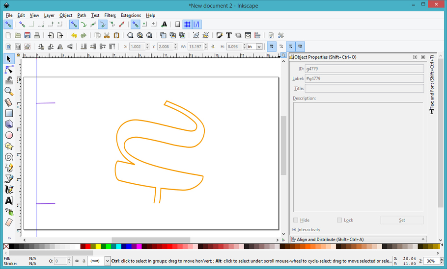
4. Save the New File immediately as a plain SVG. - Give it a name with a part number in it…ie: “Ferguson file - Part 1”
5. Repeat for the remaining sections.
“Ferguson file - Part 2”
“Ferguson file - Part 3”
“Ferguson file - Part 4”
…etc. etc. etc.
Okay that creates the files you need. How you use them is…
Part Five: How to Use the Passthrough.
1. You print out a version of the Passtrhough jigs here: Either the left or right facing set, depending on which side you set the marks up on.
(Or you can print one of each and just hang on to them for the next project.)
2. You will need to anchor your tray in the machine. I like to use these boots. You can also just tape the tray into place with a couple of strips of Gorilla Tape. Just make sure the tray is level and don’t let it wiggle.
3. If you have not yet run the Improved Calibration program, GET IT, and run it. It helps to improve the overall alignment for the lid camera, particularly out at the edges of the bed.
4. You will tape one of the jigs flush against the side of your tray, so that it cannot move! You need to be able to see both sets of “marks” on the screen display, both the marks on the jig and the marks on the material, and they need to fall over the grid, so space it accordingly. You will probably have to insert it through the passthrough slot…just make sure it is flush against the tray edge. (And don’t forget to remove the rear passthrough cover before you get started.)
5. Then you load File 1.
(When you shift the files, you have to shift everything together so use CTRL+A to select everything, and just nudge it up or down using the arrow keys. DO NOT let the index marks shift relative to the other cut lines. If you have a problem doing this, draw a rectangle around both the marks and the cut lines, make that rectangle a different color, and then set it to Ignore in the Glowforge interface. It will force the parts to maintain relative distance, but you can and should completely ignore it in the file once you open it in the interface.) Try to position it on the screen so that the index mark falls close to the edge of the material. Use the Set Focus tool near the marks to improve the alignment accuracy. Align the entire design so that the index marks look like they are right next to the equivalent marks on the jig. (The 8" marks in this case.)
6. Lightly score the file index marks on the material without cutting anything yet. Adjust your design up or down and do another test score until the scored lines land right next to the 8" lines on the jig. (Walk over and look at it, don’t rely on the screen view.) When it is exact, score it darkly again so you know which one it is.
7. Cut Part 1. Be sure to check for complete cut through using a pick and without shifting the material - you don’t get a second chance. If it’s not completely cut through, send the cut a second time, without moving the material or the image on the screen.
8. After the cut is complete, shift your material forward until the bottom mark you scored on it lines up perfectly alongside the top 8" mark. Load the second file to the GFUI and place the top index line near the top 8" mark and the bottom index line near the bottom 8" mark.
9. Again lightly score the index lines and adjust the design until your top index mark score from File 2 lands right on top of the bottom mark scored in the first file. Once you have that adjusted, you can send the second section to cut.
10. Continue through each of the sections.
VERY IMPORTANT POINTS:
Make sure you have everything completely flush tight against the ruler the entire time - a tiny bit of skew is going to show up big time in the results. If your masking extends over the edge of the material, cut it off flush before you start. It’s enough to make a huge difference. You also have to keep the material as flat as possible on the bed…use pins wherever possible, and make sure you have the front and back of the material supported going into and out of the machine. Large sheets are going to bow if they’re not supported. That’s going to throw off alignment.
One other handy tip…keep a roll of masking tape handy to tape partial cuts to the backing material before shoving it through the rear slot. Otherwise the partial cuts will likely break and hang up from lack of support.
Okay, that’s about it. Good luck. ![]()