Planar butt jointing techniques

Oh snap. This one:

https://www.urbanelementz.com/quilting-designs/pantographs-e2e/a-little-bit-this.html

3 Likes

Do it!!! Do it NOW!!!

3 Likes

At some point you might think inlay rather than joints.

As per my “rules” in the original post, there were to be no freefloating parts, so it isn’t really inlay. Complicated joints use a lot of the same skills and design principles, but to me it’s not inlay until you have “islands”.

See my other posts for inlay work, such as my Phoenix:

Or my Aries box:

4 Likes

Hi. I have an Accuslice and can cut wood to any thickness including 1/8 " thick. I am curious about the swirl pattern. if you but the two woods together did you reverse the pattern or cut one and did an overlay on the second piece of wood to create cut lines?

Your question is answered in the thread already, you should go back and read everything, but here are a couple of pull quotes that are relevant:

And as for path manipulation and process:

BUT! I have since changed my method here. Note, this is all in Inkscape.

I don’t use the subtraction method anymore, because of deficiencies in Inkscape. It’s not terrible but I don’t always like how Inkscape manages nodes when you do booleans. Sometimes it’s so bad that it ruins the path and offsetting gets weird, so now my new technique is to do this:

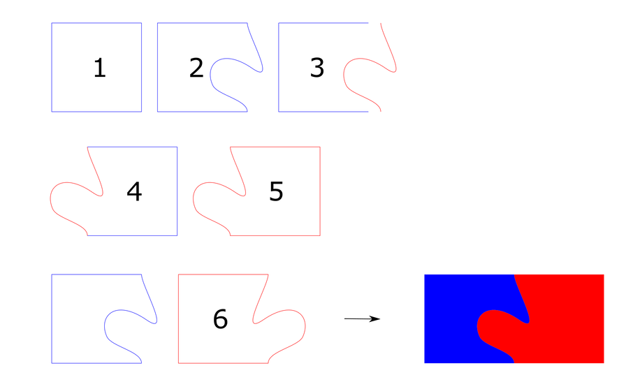
1,2. Make my desired curve exactly as I want it. I started with a rectangle and manipulated the side with the node tool.

  1. Make a copy of the shape #2, and break the new copy #3 where appropriate (in this case, the corners) to extract the actual curve (in red) in question as a separate path object.

4,5: Join the now isolated curve to its mated shape using direct node manipulation.

  1. Flip one piece horizontally so that you can flip the two resulting cut pieces (not always necessary, depend on the symmetry of your curve. It never hurts to do it even if you have the correct symmetry axis, so I just do it.)

Kerf adjust both pieces, and you’re good to go.

For a ton more of info on these techniques and some practical examples, look at my series of posts about trays. In no particular order:

Some other relevant posts that rely on the techniques here in some way:

19 Likes

Did I miss one of your posts - how does one do "light constant kerf correction?

By light I mean “snug — but not hammer — fit”. Typically 0.005-0.006 for most woods.

Constant means: do it to all pieces, don’t forget or try to skimp by only correcting one half.

1 Like

so to further the point - do you shrink one piece (one curve?) by .0005 or something?

Nope, exactly the opposite.

I use inkscape - set stroke to be 0.006”, then use the “stroke to path” function to offset the original path. I find that it gives better result than the offset function in some cases.

8 Likes

Hmm I should crosslink wave tray here:

3 Likes

Wow! I’ve had similar ideas running thru my mind, but could quite bring it to the workbench. You, my friend are my new hero. The exotics add such an amazing . contrast. Thank you for sharing!-ok+8i

1 Like

Too bad I can’t LIKE this post again! Truly still amazing.

3 Likes

You’re now my favorite person! :smiley:

2 Likes

That wenge/padauk piece is still one of my favorite things ever. :heart:

2 Likes

I use inkscape - set stroke to be 0.006”, then use the “stroke to path” function to offset the original path. I find that it gives better result than the offset function in some cases.
[/quote]

@evansd2 Wondering if you would be willing to provide more detail on how you actually do the kerf compensation. It’s making me nuts that complex curves don’t offset in a way that allows them to align when joined. I can see the problem in software. If I offset the wavy curves pictured here at .003",


and then overlay one onto the other to check the geometry, the two curves no longer match. How do you offset in a way that preserves the curves on both pieces? Thanks!

1 Like

You’ll want to close your shapes and then kerf adjust each shape individually using a stroke line thickness equal to your kerf. It’s explained here:

4 Likes

Thanks @Jules ! I read the document, and it makes total sense to me. So if Inkscape isn’t a great solution for kerf adjustment on complex shapes, which is my particular problem, what is? Or is my wavy line example relatively simple and Inkscape would be appropriate?

I do all my work in inkscape and I use the stroke to path method to kerf adjust, just like Jules recommends. Given that you’re trying to emulate my curve I’d say you’ll be fine.

I’m not at my pc so can’t look directly at your curve, but if it’s got a lot of weird nodes sometimes that can cause issues with stroke to path. I’ll have to dig deeper in a bit… but the bottom line is that you want your path to be closed, you want your nodes to be necessary (no double nodes), and ideally sharp corners are to be avoided, as they can lead to unsightly overburn.

I talk a bit more at length in my various tray posts. You might want to search the forum for “@evansd2 tray in:first”, it’s where I apply a lot of these methods and discuss technique more deeply.

5 Likes

Thanks so much @evansd2. I’ve read your posts, which are the inspiration for all of this! It’s the actual process of kerf correction that I wasn’t clear about, and now I have a much better understanding. Good reminder about sharp curves too…The other challenge for me is that I am very literate in Vcarve Pro from CNC work, and minimally so in Inkscape. So I’ve been trying to do as much as possible in Vcarve before dealing with Inkscape. I know that I need to learn Inkscape or AI to take my laser design to the next level…

Love this forum and all the support! Thank you.

1 Like