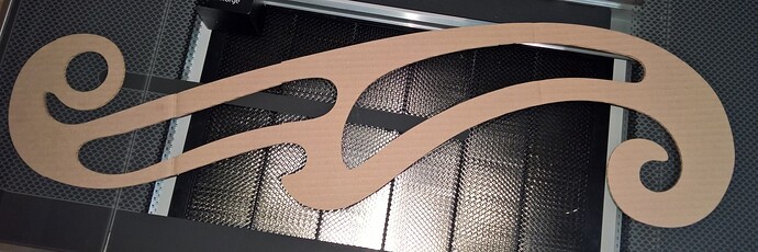
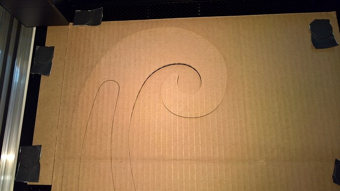
I wanted to test some theories about pass-through use and to create a tutorial about how we can work around the camera alignment inaccuracies in the current state of the Glowforge software. To spoil the ending, here’s the final product:
I’ll be using Adobe Illustrator CC 22.0.1 (current version) primarily because I have a subscription via work. However, I am a total newbie with AI, so please feel free to point out other/better ways to do things if I end up doing them the hard way.
I wanted a simple shape that would likely point out any flaws in positioning. I found a set of french curves in an SVG file here: Set of French curve templates | CRAFTSMANSPACE, licensed with the Creative Commons Attribution-ShareAlike 3.0 Unported (CC BY-SA 3.0).
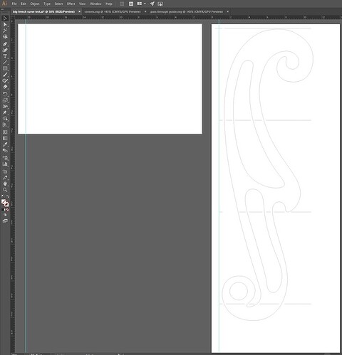
I figured expanding one of the more curly french curves to something over 30" long would provide some good practice. To cut this we need to create a multi-operation cut file with “panels” of cuts overlaid on each other within a 12 x 20 artboard. This artboard size will force absolute positioning in the GFUI.
The plan for cutting this piece will use a guide along the left edge that stays in place (via magnets) on the crumb tray. The first operation will mark the top of the first panel with a fiducial mark on the guide. Each panel will also mark the edge of the material being cut at the very bottom of the panel, exactly 10" down in the design. After each cut, the material will be pushed through by 10", the newest “bottom of panel” fiducial aligned with the mark on the guide.
Creating the Guide
I did some experimenting with a 12" x 20" artboard and some one-inch squares to see just where in the GFUI these would show up. I found that (0, 0) in the artboard aligns to (0, 0) in the GFUI (the top left corner of the bed image). However, it would not allow a square positioned at (0, 0) to be included in the design. Nudging it (in Illustrator) to (0.01", 0.01") allows it to be cut. Running some light scores determined that with material pushed up against the left edge of the crumb tray, the X position of 0 in the design is about 0.66 on the material (on my machine, YMMV). After determining that, I made a rectangle 1.5" wide and 10.5" tall and cut this out of a piece of cardboard from the box I was cutting up for this test (a used moving box). This would not take too much width and would be fairly easy to hold down with magnets.
Creating the Design
I created Artboard 1 as 12" x 20" to be my “output” artboard. This is where the final design will be placed.
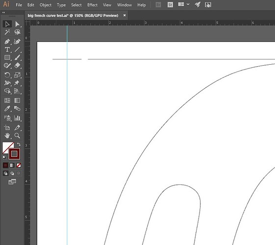
I created Artboard 2 as 36" x 14" to hold my overall, unsliced design. I selected one of the french curves and placed it on Artboard 2 and scaled it to fill most of the height. I then used the Direct Selection tool to select the individual curves and looked for incongruities in the design. I found two points that were very close to each other, but not quite the same. I used the point averaging function to split the difference and make them a single point.
With the guide being 1.5" wide, the right side will be at 0.84" from the left side of the Artboard (1.5" - 0.66" margin = 0.84". To help align things, I placed a vertical guide at 0.84" on each artboard. This guide shows where the right edge of the guide will be and the left edge of the material being cut.
I’m going to slice the design into panels 10 inches high.
On Artboad 2, I put a score spanning guide, being 0.4" on either side of the edges.
The part on the left side of the guide will mark the guide to be the fiducial marker that subsequint marks are aligned with as we move the material. The first mark is at a Y position of 0.5". Since the panels are spaced every 10 inches, the following marks are at 10.5", 20.5", and 30.5". These marks are all just 0.4" on the right side of the guide–no need to re-mark the guide on these.
So that we can clearly see where the discontinuities between cuts will be, I’m also putting score lines across the design aligned with the fiducial marks.
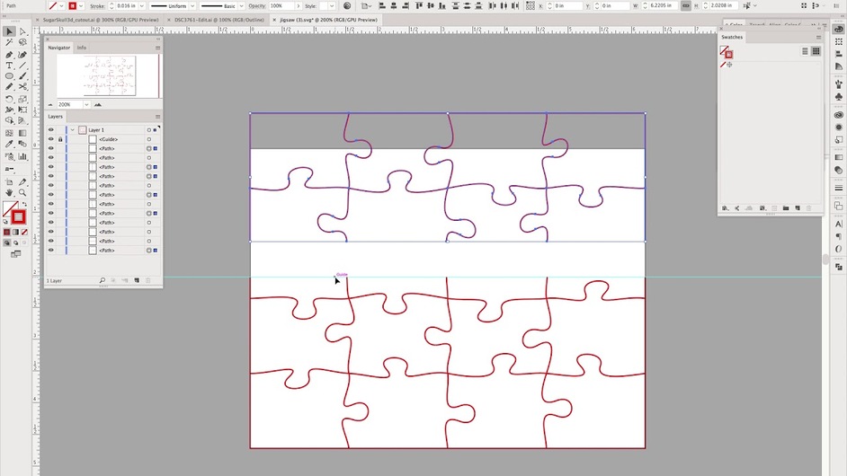
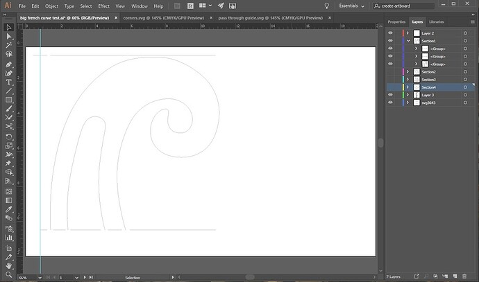
Now, we need to cut the big design into pieces. One way to do this in Illustrator is to draw a line at the dividing line and use the “Object->Path->Divide Objects Below” tool. This will slice the paths of our design along the line. It also closes off the paths–something we don’t want–possibly because the curves we’re cutting are closed paths. To fix that, I used the scissor tool to remove the added line segments. At each cut, there are two lines to be removed, one from each of the split paths. For this design the process isn’t too bad. If we were filling these shapes, this closing would be appropriate. If someone knows of a tool that slices without closing, that would be nice to know about.
I grouped the pieces of the french curve within each section to make it easy to select them in the following steps.
Next we copy each section and move it to the 12 x 20 artboard. We are going to stack these up so that the top of each section starts at the same Y-value in the final design.
To make the copies, we select the group containing the design, and the group containing the fiducial(s) being included with the group. The first section we’ll copy both the top and bottom fiducials. The bounding box of everything being copied (and therefore the position shown for the group) will be the position of the top fiducial. We’ll set the Y value to 0.5" and the X value to the same value as in the source image.
For each of the other sections, we’ll only copy the bottom fiducial in that area. Again we can position the whole group so the X value matches the original X value of the fiducial in the source design, and the Y value will be 0.5".
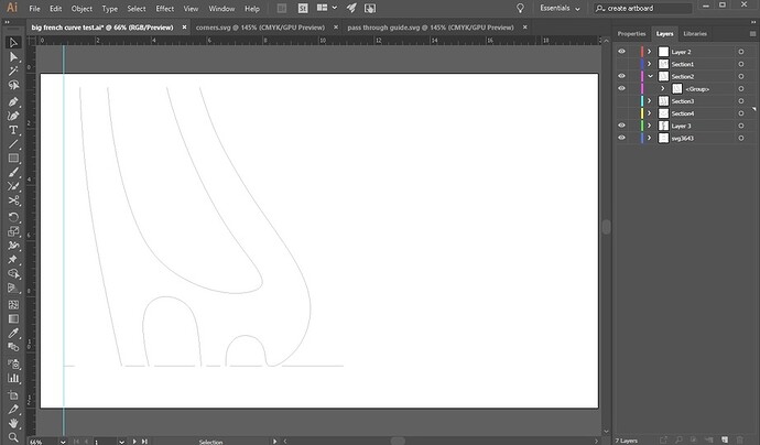
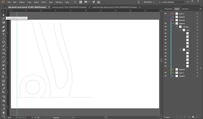
Create a new layer for each section, putting the objects in that layer. This lets us easily view them individually on the output artboard.
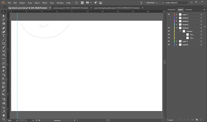
For the last section, to help with alignment I initially included the top fiducial. This allowed me to position it the same way as the others. I then deleted these scores since they were included in Section 3.
Now we need to assign colors to each part. We need to cut the design and lightly score the fiducials in each section, and we need to process the sections in sequence. We’ll use the colors that @marmak3261 determined to order the operations in the GFUI (Custom Inkscape, Illustrator, CorelDraw and Affinity Designer Color Palettes for ordering operations in GFUI):
0 0 0 1 black (#000000)
0 0 255 2 dark blue (#0000ffff)
0 100 0 3 dark green (#006400ff)
0 100 255 4 navy blue (#0064ffff)
0 255 0 5 bright green (#00ff00ff)
0 255 255 6 aqua blue (#00ffffff)
100 0 0 7 brown (#640000ff)
100 0 255 8 purple (#6400ffff)
100 255 0 9 lime green (#c8ff00ff)
255 0 0 10 red (#ff0000ff)
255 0 255 11 magenta (#ff00ffff)
255 100 0 12 orange (#ff6400ff)
255 255 0 13 yellow (ffff00ff)
We’ll only need 7 of those since we don’t need to print a fiducial on the last section.
Section 1 fiducials (both top and bottom): black
Section 1 design: dark blue
Section 2 fiducial: dark green
Section 2 design: navy blue
Section 3 fiducial: bright green
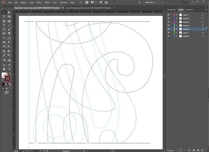
Section 3 design: aqua blue (cyan)
Section 4 design: brown
So here we have the final design with all of the layers shown.
Running the Cuts
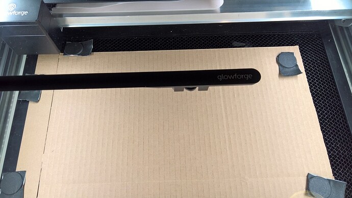
Here we see the initial placement of the cardboard to be cut alongside the guide. Note there’s a bit of a gap at the top surface, the bottom surface is pushed up against the guide. Magnets are placed well outside of the area to be lasered.
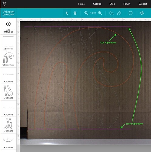
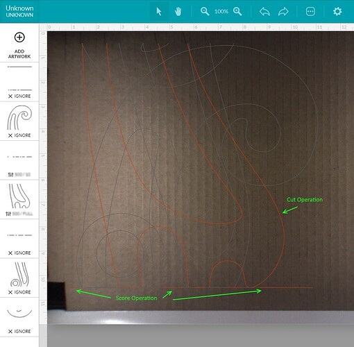
Loading the design in the GFUI and setting the score for the fiduciary marks (top and bottom) and the cut operation.
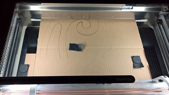
After the cut:
The weight of the cardboard out the front of the machine made the curvy part pop up during the cut. It will be important to support the material front and back.
You can see the bottom fiducial mark here.
And here it is aligned for cut 2.
Ignore the first two operations and set the next two. Not much color difference between the two in the UI (not the same colors as in the design).
As the 2nd cut is underway, I caught this picture of the first cut partway out the back slot.
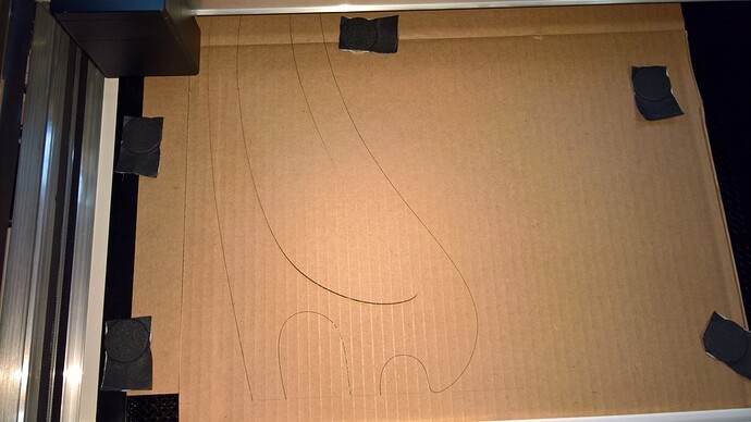
After the 2nd cut:
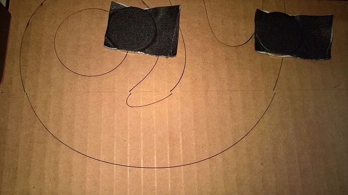
The last cut (cut 4) I didn’t have properly aligned against the guide. It was a short piece of cardboard left, and I didn’t notice it was at an angle.
This led to a significant error in the cuts
I repositioned it a little and re-ran the cut, leaving the final piece with less error.
Learnings
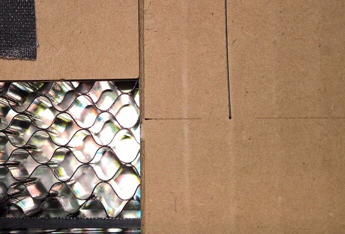
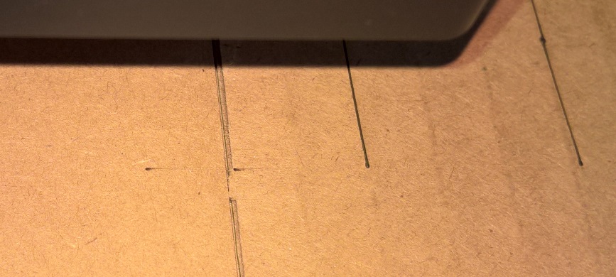
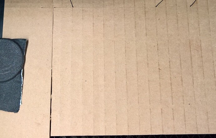
Working with cardboard did not allow for rigid alignment. This led to a little error to in the X axis, but the Y axis worked quite well. Here’s the juncture between cuts 1 & 2:
And between 2 & 3
Summary
That was my first project since cutting the Founder’s Ruler, and the first I’ve designed myself. I hope this can help others use the pass-through slot effectively. I think using non-squishy material for the guide and the project would have resulted in much more accuracy in the horizontal placements.
A Final Note on Alignment
The guide and the material must be the same thickness. If you don’t have the same thickness, you will likely experience Parallax Error when trying to line up the fiducial marks. Here’s a picture to illustrate.
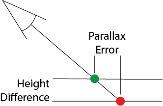
Edited: Fixed spelling error on parallax error diagram.
Also, be sure to read the messages below. There are some great tips and further ideas and refinements.


 might get the auto-align working by the time I get to pass-through. That is a nice feature, but I went Pro mostly for filter, increased power, and active cooling.)